Laat Een Bericht Achter
Als u geïnteresseerd bent in onze producten en meer details wilt weten, laat dan hier een bericht achter. We nemen zo snel mogelijk contact met u op.

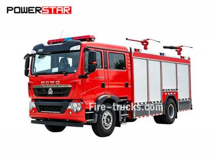
Reparatiehandleiding voor de 4HK1-motor van de Isuzu NPR brandweerwagen.
De Isuzu brandweerwagen 4HK1-TC motoronderhoudshandleiding, ook wel motorreparatiehandleiding genoemd. Isuzu brandweerwagen of Ingenieursboek van Isuzu brandweervoertuig .
De Isuzu Fire Truck 4HK1-TC-motor is een krachtige dieselmotor die veelvuldig in brandweerwagens wordt gebruikt en bekendstaat om zijn betrouwbaarheid, duurzaamheid en hoge efficiëntie. Om een stabiele werking van de motor op lange termijn te garanderen, zijn regelmatig onderhoud en reparaties essentieel. Dit artikel geeft een korte introductie van de belangrijkste onderwerpen in de onderhoudshandleiding van de Isuzu Fire Truck 4HK1-TC-motor, zodat onderhoudspersoneel de handleiding beter kan begrijpen en bedienen.
1. Motoroverzicht
De 4HK1-TC-motor is een viercilinder lijnmotor met turbodiesel, een cilinderinhoud van 5,2 liter en een maximaal vermogen van 190 pk. De motor maakt gebruik van een geavanceerd common-rail brandstofinjectiesysteem en een elektronische regeleenheid (ECU) om een hoger brandstofrendement en lagere emissies te realiseren.
2. Dagelijks onderhoud
Dagelijks onderhoud is de basis voor een goede werking van de motor. In het onderhoudshandboek staan de dagelijkse controlepunten gedetailleerd beschreven, waaronder het controleren van het olie- en koelvloeistofpeil, het reinigen of vervangen van het luchtfilter, het vervangen van het brandstoffilter, enzovoort. Daarnaast geeft het handboek ook aanbevelingen voor het regelmatig vervangen van de motorolie en het oliefilter, doorgaans elke 5.000 kilometer of elke 6 maanden.
3. Foutdiagnose
De onderhoudshandleiding bevat een gedetailleerde procedure voor foutdiagnose, waarmee onderhoudspersoneel snel problemen kan opsporen en oplossen. De handleiding vermeldt veelvoorkomende foutcodes en hun betekenis, en biedt bijbehorende oplossingen. Als de motor bijvoorbeeld te weinig vermogen levert, begeleidt de handleiding het onderhoudspersoneel bij het controleren van het brandstofsysteem, de turbocompressor en het uitlaatsysteem, enzovoort.
4. Revisie en vervanging van onderdelen
Voor motoren die een revisie of vervanging van onderdelen nodig hebben, biedt de onderhoudshandleiding gedetailleerde stappen en voorzorgsmaatregelen. Bijvoorbeeld, bij het vervangen van belangrijke componenten zoals zuigerveren, klepgeleiders en lagers, beschrijft de handleiding de stappen voor demontage en montage, evenals het benodigde gereedschap en de aanhaalmomenten.
5. Veiligheidsmaatregelen
In de onderhoudshandleiding wordt nadrukkelijk aandacht besteed aan het belang van veilig werken. Voordat u onderhoudswerkzaamheden uitvoert, moet u ervoor zorgen dat de motor volledig is afgekoeld en de stroomtoevoer is uitgeschakeld. Daarnaast bevat de handleiding ook aanbevelingen voor het gebruik van persoonlijke beschermingsmiddelen, zoals handschoenen, een veiligheidsbril en beschermende kleding.
Artikel 1A
Motorbesturingssysteem
Inhoudsopgave
Pagina
[if supportFields]> TOC \h \z \t "1A,1,1A-,2"
Motorbesturingssysteem
[if supportFields]>
4
[if gte mso 9]>
Voorzorgsmaatregelen
[if supportFields]>
4
[if gte mso 9]>
Functie en werkingsprincipe
[if supportFields]>
5
[if gte mso 9]>
Onderdelenconfiguratiediagram
[if supportFields]>
21
[if gte mso 9]>
Schakelschema
[if supportFields]>
25
[if gte mso 9]>
Hoe de storing te diagnosticeren
[if supportFields]>
42
[if gte mso 9]>
Storingsdiagnoseprocedures met behulp van een storingsdiagnosemeter
[if supportFields]>
48
[if gte mso 9]>
Overzicht van de functionele controle
[if supportFields]>
50
[if gte mso 9]>
Navraag
[if supportFields]>
51
[if gte mso 9]>
Controle van het motormanagementsysteem
[if supportFields]>
53
[if gte mso 9]>
Lijst met gegevens van de foutdiagnosemeter
[if supportFields]>
55
[if gte mso 9]>
Inhoud van de gegevenslijst van de foutdiagnosemeter
[if supportFields]>
58
[if gte mso 9]>
Uitgang van de foutdiagnosemeter
[if supportFields]>
64
[if gte mso 9]>
Storing bij het starten van de diagnosemeter
[if supportFields]>
65
[if gte mso 9]>
Storing in de communicatie van de diagnosemeter (referentie)
[if supportFields]>
67
[if gte mso 9]>
Communicatiefout met ECM (referentie)
[if supportFields]>
71
[if gte mso 9]>
Start systeembevestiging
[if supportFields]>
74
[if gte mso 9]>
Motor MIL-lampje brandt, bevestiging van het elektrische circuitsysteem
[if supportFields]>
77
[if gte mso 9]>
Bevestiging van het knipperende motorstoringslampje (MIL) en het elektrische circuitsysteem
[if supportFields]>
78
[if gte mso 9]>
inspectie van het uitlaatgasrecirculatiesysteem (EGR)
[if supportFields]>
80
[if gte mso 9]>
inspectie van het opwarmregelsysteem
[if supportFields]>
84
[if gte mso 9]>
inspectie van het uitlaatrem-/luchtinlaatbeperkingssysteem
[if supportFields]>
87
[if gte mso 9]>
Overzicht van diagnostische foutcodes (DTC's)
[if supportFields]>
92
[if gte mso 9]>
DTC P0016 (Flashcode 16)
[if supportFields]>
95
[if gte mso 9]>
DTC P0087 (Flashcode 225)
[if supportFields]>
97
[if gte mso 9]>
DTC P0088 (Flashcode 118)
[if supportFields]>
103
[if gte mso 9]>
DTC P0089 (Flashcode 151)
[if supportFields]>
109
[if gte mso 9]>
DTC P0091, P0092 (Flashcode 247)
[if supportFields]>
112
[if gte mso 9]>
DTC P0093 (Flashcode 227)
[if supportFields]>
116
[if gte mso 9]>
DTC P0107, P0108 (Flashcode 32)
[if supportFields]>
122
[if gte mso 9]>
DTC P0112, P0113 (Flashcode 22)
[if supportFields]>
127
[if gte mso 9]>
DTC P0117, P0118 (Flashcode 23)
[if supportFields]>
132
[if gte mso 9]>
DTC P0122, P0123 (Flashcode 43)
[if supportFields]>
137
[if gte mso 9]>
DTC P0182, P0183 (Flashcode 211)
[if supportFields]>
142
[if gte mso 9]>
DTC P0192, P0193 (Flashcode 245)
[if supportFields]>
147
[if gte mso 9]>
[if supportFields]> DTC P0201, P0202, P0203, P0204 (Flashcode 271, 272, 273, 274)................................................... 1A-157
DTC P0217 (Flashcode 542)...................................................................................................... 1A-170
DTC P0219 (Flashcode 543)...................................................................................................... 1A-172
DTC P0234 (Flashcode 42)........................................................................................................ 1A-175
DTC P0299 (Flashcode 65)........................................................................................................ 1A-178
DTC P0335 (Flashcode 15)........................................................................................................ 1A-182
DTC P0336 (Flashcode 15)........................................................................................................ 1A-187
DTC P0340 (Flashcode 14)........................................................................................................ 1A-190
DTC P0341 (Flashcode 14)........................................................................................................ 1A-195
DTC P0380 (Flashcode 66)........................................................................................................ 1A-198
DTC P0381 (Flashcode 67)........................................................................................................ 1A-201
DTC P0404 (Flashcode 45)........................................................................................................ 1A-205
DTC P0409 (Flashcode 44)........................................................................................................ 1A-208
DTC P0477, P0478 (Flashcode 46)............................................................................................. 1A-212
DTC P0500 (Flashcode 25)........................................................................................................ 1A-216
DTC P0502, P0503 (Flashcode 25)............................................................................................. 1A-218
DTC P0563 (Flashcode 35)........................................................................................................ 1A-223
DTC P0601 (Flashcode 53)........................................................................................................ 1A-225
DTC P0602 (Flashcode 154)...................................................................................................... 1A-226
DTC P0604, P0606, P060B (Flashcodes 153, 51, 36).................................................................... 1A-228
DTC P0641 (Flashcode 55)........................................................................................................ 1A-230
DTC P0650 (Flashcode 77)........................................................................................................ 1A-233
DTC P0651 (Flashcode 56)........................................................................................................ 1A-237
DTC P0685, P0687 (Flashcode 416)........................................................................................... 1A-241
DTC P0697 (Flashcode 57)........................................................................................................ 1A-245
DTC P1093 (Flashcode 227)...................................................................................................... 1A-248
DTC P1261, P1262 (Flashcode 34)............................................................................................. 1A-253
DTC P1404 (Flashcode 45)........................................................................................................ 1A-255
DTC P1621 (Flashcode 54)........................................................................................................ 1A-257
DTC P2122, P2123 (Flashcode 121)........................................................................................... 1A-258
DTC P2127, P2128 (Flashcode 122)........................................................................................... 1A-264
DTC P2138 (Flashcode 124)...................................................................................................... 1A-270
DTC P2146, P2149 (Flashcode 158)........................................................................................... 1A-273
DTC P2228, P2229 (Flashcode 71)............................................................................................. 1A-279
DTC P253A (Flashcode 28)....................................................................................................... 1A-284
DTC P256A (Flashcode 31)....................................................................................................... 1A-287
DTC U0073 (Flashcode 84)....................................................................................................... 1A-291
Symptoomdiagnose................................................................................................................... 1A-296
Verschijnselen: Intermittatie............................................................................................................ 1A-297
Symptoom: Moeilijk starten........................................................................................................ 1A-300
Verschijnselen: Schommelingen in het toerental, onregelmatig stationair draaien of afslaan van de motor.................................................................... 1A-303
Verschijnsel: Hoog stationair toerental.................................................................................................... 1A-306
Symptoom: Noodstop......................................................................................................... 1A-307
Symptoom: Noodgeval..................................................................................................... 1A-309
Symptoom: Onvoldoende vermogen, haperende acceleratie of vertraagde reactie........................................................... 1A-311
Verschijnselen: Intermitterende werking, acceleratiestoring................................................................... 1A-314
Symptoom: Verbrandingsgeluid...................................................................................................... 1A-316
Symptoom: Laag brandstofverbruik.................................................................................... 1A-317
Verschijnsel: zwarte rook uit uitlaatgassen................................................................................... 1A-319
Symptoom: Witte rook uit uitlaatgassen.................................................................................. 1A-321
Belangrijkste sensorparameters.............................................................................................................. 1A-323
Speciaal gereedschap............................................................................................................................. 1A-325
Programma............................................................................................................................... 1A-326
Programmeerregel...................................................................................................................... 1A-326
Programma............................................................................................................................... 1A-326
Injectiepomp leren.............................................................................................................. 1A-328
Aanpassing............................................................................................................................ 1A-328
Gebruik van circuittesttools
Gebruik bij diagnose volgens het diagnoseprogramma de testlamp niet voor diagnose van het elektrische systeem van de aandrijflijn, tenzij anders aangegeven. Indien de meetsonde wel wordt gebruikt voor het diagnoseprogramma, gebruik dan de testadapterset 5-8840-2835-0.
Op de markt verkrijgbare elektrische componenten
De elektrische componenten die op de markt verkrijgbaar zijn, zijn de componenten die in de handel worden aangeschaft om in het voertuig te worden geïnstalleerd. Aangezien met deze componenten geen rekening wordt gehouden tijdens de ontwerpfase van het voertuig, is het belangrijk om hier rekening mee te houden bij het gebruik ervan.
Voorzichtigheid:
De in de handel verkrijgbare elektrische componenten voor voeding en aarding moeten worden aangesloten op het circuit, onafhankelijk van het circuit van het elektrische besturingssysteem.
Hoewel in de handel verkrijgbare elektrische componenten gebruikt kunnen worden, kunnen deze in sommige gevallen storingen in het elektrische besturingssysteem veroorzaken. Dit geldt ook voor apparaten die niet op het elektrische systeem zijn aangesloten, zoals bijvoorbeeld een mobiele telefoon of radio. Controleer daarom bij de diagnose van de aandrijflijn eerst of dergelijke in de handel verkrijgbare elektrische componenten zijn geïnstalleerd. Zo ja, verwijder ze dan uit het voertuig. Als de storing na verwijdering van de componenten nog steeds aanwezig is, volg dan de algemene diagnoseprocedure.
Schade door ESD
Omdat de elektronische onderdelen in het elektrische besturingssysteem op extreem lage spanningen werken, zijn ze gemakkelijk beschadigd door elektrostatische ontlading (ESD). Sommige elektronische onderdelen raken beschadigd door statische elektriciteit bij een spanning lager dan 100V, wat voor het menselijk oog niet waarneembaar is. Voor een waarneembare ESD-reactie is een spanning van 4000V nodig. In veel gevallen draagt het menselijk lichaam statische elektriciteit met zich mee, waarbij wrijving en inductie de meest voorkomende oorzaken zijn.
● Wanneer de persoon op de stoel heen en weer beweegt, ontstaat er wrijvingselektrificatie.
● Wanneer iemand met geïsoleerde schoenen zich in de buurt van een sterk geëlektrificeerd object bevindt, treedt elektrostatische inductie op zodra de persoon de grond raakt. De persoon wordt geëlektrocuteerd wanneer ladingen van dezelfde polariteit ladingen van tegengestelde polariteit ontmoeten. Omdat statische elektriciteit schade kan veroorzaken, dient u voorzichtig om te gaan met elektronische onderdelen en deze te testen.
Voorzichtigheid:
Neem de volgende regels in acht om schade door elektrostatische ontlading te voorkomen:
● Raak de contactpinnen van de ECM-aansluiting en de elektronische onderdelen die op de achterplaat van het ECM-circuit zijn gesoldeerd niet aan.
● Pak de parken niet uit voordat de voorbereiding voor de installatie van de onderdelen is voltooid.
● Sluit de verpakking en de normale massa van het voertuig aan voordat u de onderdelen uit de verpakking haalt.
● Als u op de stoel heen en weer beweegt, vanuit een staande positie gaat zitten of het onderdeel bedient terwijl u zich over een bepaalde afstand beweegt, zorg er dan voor dat u de grond raakt voordat u het onderdeel installeert.
Motorbesturingssysteem (common rail)
Systeemoverzicht en details
Het motormanagementsysteem is het elektrische besturingssysteem dat de motor regelt om de optimale verbrandingstoestand te bereiken, afhankelijk van de rijomstandigheden. Het bestaat uit de volgende onderdelen:
● Elektronisch geregeld brandstofinjectiesysteem (common rail type)
● EGR
Daarnaast omvat het motormanagementsysteem de volgende systeemcontrolefuncties.
● Opwarmregelsysteem
● Rotatievermogen van de motor
● Communicatie- en zelfdiagnosefunctie
[endif]
[if gte vml 1]>
Elektronisch geregeld brandstofinjectiesysteem (common rail type)
Het common rail-systeem bestaat uit een drukvat en een injector. Het drukvat is ontworpen om de brandstof onder druk op te slaan en wordt de common rail genoemd. De injector is voorzien van een elektronisch gestuurde magneetklep om de brandstof onder druk in de verbrandingskamer te injecteren. Omdat de injectieregeling (injectiedruk, injectiesnelheid en injectietijd) wordt aangestuurd door de ECU (Engine Control Module), maakt het common rail-systeem een onafhankelijke regeling van het motortoerental en de belasting mogelijk. Zelfs bij een laag motortoerental kan een stabiele injectiedruk worden gehandhaafd, wat de specifieke zwarte rook bij het starten en accelereren van de dieselmotor aanzienlijk vermindert. Door deze regeling worden de uitlaatgassen schoner, neemt het uitlaatgasvolume af en wordt het vermogen verhoogd.
Controle van het injectievolume
Het systeem stuurt de injectorwikkeling aan op basis van het signaal dat wordt verkregen uit het motortoerental en de stand van het gaspedaal, en regelt zo de brandstofinjectiehoeveelheid om het optimale volume te bereiken.
Injectiedrukregeling
Om hogedrukinjectie mogelijk te maken, zelfs bij een laag motortoerental, moet de brandstofdruk in de common rail worden geregeld. De juiste druk in de common rail moet worden berekend op basis van het motortoerental en het brandstofinjectievolume. De juiste hoeveelheid brandstof wordt vervolgens via de injectiepomp onder druk naar de common rail geleid.
Controle van het injectietijdstip
Het vervangt de timingfunctie en berekent het juiste brandstofinjectiemoment op basis van het motortoerental en het injectievolume, waarna het de injector aanstuurt.
Controle van de injectiesnelheid
Om de verbrandingsefficiëntie van de cilinder te verbeteren, wordt een kleine hoeveelheid brandstof ingespoten (voorinjectie) voor de ontsteking. Na de ontsteking vindt de tweede injectie plaats (hoofdinjectie). Het tijdstip en de hoeveelheid injectie worden geregeld via de injector (de injectorbobine).
 [endif]
Brandstofsysteem
Het common rail-systeem bestaat uit 2 brandstofdruksystemen.
● Lagedruk-inlaatleiding: tussen de brandstoftank en de injectiepomp
● Hogedrukleiding: tussen de injectiepomp en de injector
De brandstof wordt vanuit de brandstoftank in de injectiepomp gezogen en in de pomp onder druk gezet om de common rail te voeden. Op dit punt, Het signaal van de ECM stuurt de aanzuigregelklep (de common rail-drukregelaar) aan om de hoeveelheid brandstof die aan de common rail wordt toegevoerd te regelen.
Schema van het brandstofsysteem
[if gte vml 1]>
|
Sleutel 1. Common Rail 2. Drukbegrenzingsklep 3. Retourleiding injector 4. Injector 5. Brandstofretourleiding 6. Brandstoftoevoerleiding |
7. Brandstoftank 8. Ontluchtingsklep 9. Startpomp 10. Brandstoffilter (met olie-waterafscheider) 11. Retourklep 12. Brandstofinjectiepomp |
EGR (Uitlaatgasrecirculatie)
Het EGR-systeem recirculeert een deel van de uitlaatgassen naar het inlaatspruitstuk en vermindert daardoor de uitstoot van stikstofoxiden (NOx). Dankzij het EGR-systeem worden zowel de rijeigenschappen als de uitstoot van uitlaatgassen verminderd. De stuurstroom van het EGR-systeem stuurt de magneetklep aan, waardoor de kleplift van het EGR-systeem wordt geregeld. Bovendien detecteert dit systeem de werkelijke kleplift met behulp van een EGR-positiesensor voor een nauwkeurige regeling van het EGR-systeem.
De EGR-functie treedt in werking wanneer aan de voorwaarden voor motortoerental, koelvloeistoftemperatuur, inlaattemperatuur en luchtdruk is voldaan. Vervolgens berekent het systeem de klepopening op basis van het motortoerental en het gewenste brandstofinjectievolume. Aan de hand van de berekende klepopening bepaalt het systeem de aansturing van de magneetklep en stuurt deze vervolgens aan. Tijdens de EGR-werking wordt de gasklep gesloten om de druk in het inlaatspruitstuk op de gewenste waarde te laten komen.
[if gte vml 1]>
[endif]
[als !mso]
|
[endif]
[als !mso]
|
[endif]
[als !mso]
|
[endif]
[als !mso]
|
|
Sleutel 1. ECM 2. EGR-positiesensor 3. EGR-klep 4. EGR-koeler |
5. Inlaatgasklep
|
Opwarmingscontrole
Opwarmregelsysteem
Het opwarmregelsysteem is ontworpen om het starten van de motor bij lage temperaturen te vergemakkelijken en de witte rook en het geluid te verminderen. Wanneer de startschakelaar is ingeschakeld, detecteert de ECU de temperatuur van de koelvloeistof aan de hand van het signaal van de koelvloeistoftemperatuursensor (ECT) om de opwarmtijd aan te passen en de juiste startomstandigheden voor de motor te creëren. Bovendien zorgt de restwarmte van de opwarming ervoor dat het stationair toerental stabiel blijft. De ECU bepaalt de opwarmtijd op basis van de koelvloeistoftemperatuur om het opwarmrelais en het controlelampje te activeren.
[endif]
[if gte vml 1]>
Overzicht van de bediening van de uitlaatrem
De uitlaatpijp van de uitlaatrem is voorzien van een klep. Door deze klep te sluiten, kan de weerstand van de uitlaatslag worden verhoogd en het motorremeffect worden versterkt. De uitlaatremklep werkt op basis van de vacuümdruk. Deze vacuümdruk wordt geregeld door het openen en sluiten van een magneetklep. De ECU activeert de magneetklep als het motortoerental boven de 575 tpm ligt en aan alle voorwaarden voor de werking van de uitlaatrem is voldaan.
Bedrijfsomstandigheden van de uitlaatrem
● Uitlaatremschakelaar ingeschakeld
● Gaspedaal niet ingedrukt
● Er wordt geen afwijking gedetecteerd in de gaspedaalpositiesensor (APP), het uitlaatremcircuit, de koppelingsschakelaar, de APP-sensorschakelaar, de A/D-schakelaar, enz.
● Koppelingspedaal niet ingedrukt
● Systeemspanning hoger dan 24V
● Voertuigsnelheid overschrijdt het opgegeven bereik
ECM
Overzicht van ECM
[if gte vml 1]>
De ECM (Engine Control Module) monitort continu de informatie van elke sensor om de aandrijflijn te regelen. De ECM voert systeemdiagnostiek uit om problemen met de werking van het systeem te detecteren, de bestuurder te waarschuwen via het motorstoringslampje (MIL) en tegelijkertijd foutcodes (DTC's) te registreren. De DTC's identificeren de probleemzone en helpen de monteur daarbij.
ECM-functies
De ECM (Engine Control Module) levert een spanning van 5V om diverse sensoren en schakelaars van stroom te voorzien. Omdat de stroom echter via de weerstand van de ECM wordt geleverd, zal het testlampje dat op het circuit is aangesloten niet branden, zelfs niet bij een zeer hoge weerstand. In sommige gevallen kan een gewone voltmeter geen correcte meting weergeven omdat de weerstand te laag is. Om een correcte meting te verkrijgen, dient u een digitale multimeter met een ingangsimpedantie van minimaal 10 MΩ te gebruiken (5-8840-2691-0). De ECM regelt het massacircuit of het voedingscircuit via een transistor of andere eenheid en stuurt daarmee het uitgangscircuit aan.
ECM- en samenstellingsonderdelen
De ECM kan een hoge stuurprecisie en brandstofefficiëntie bereiken met behoud van de gespecificeerde uitlaatgasemissies. De ECM bewaakt de motor- en voertuigprestaties via de krukaspositiesensor (CKP) en de voertuigsnelheidssensor (VSS), enzovoort.
ECM-spanningsbeschrijving
De ECM past de standaardspanning toe op elke schakelaar en sensor. Dit komt doordat de weerstand van de ECM erg hoog is, terwijl de spanning die op het circuit wordt aangelegd laag is. Het testlampje zal niet oplichten, zelfs niet als het op het circuit is aangesloten. Omdat de ingangsimpedantie van de voltmeter die doorgaans door monteurs wordt gebruikt erg laag is, geeft de voltmeter soms geen correcte waarde weer. Gebruik in dat geval een digitale multimeter met een ingangsimpedantie van 10 MΩ (5-8840-2691-0) om de juiste spanningswaarde te verkrijgen.
De ECM-ingangs-/uitgangseenheid is uitgerust met een analoog-digitale converter, signaaldemping, teller en speciale actuator. ECM kan de meeste componenten aansturen via de elektronische schakelaar.
EEPROM
EEPROM is een permanente opslagchip die op de achterplaat van de ECM is gesoldeerd. Om de aandrijflijn te besturen, stuurt de ECM het benodigde programma en kalibratiebericht naar de EEPROM.
Anders dan ROM kan EEPROM niet worden vervangen. Als er een defect aan de EEPROM wordt geconstateerd, moet de ECM direct worden vervangen.
Overwegingen bij ECM-reparatie
De ECM is bestand tegen de algemene stroom die relevant is voor het rijden met een voertuig. Voorkom overbelasting van het circuit. Sluit tijdens de open-circuit- en kortsluitingstest het ECM-circuit niet aan op de massadraad en sluit geen spanning aan, tenzij anders aangegeven. Gebruik voor dergelijke circuittests een digitale multimeter (5-8840-2691-0).
 [endif]
De injectiepomp is het kernonderdeel van een common rail elektronisch brandstofinjectiesysteem. De injectiepomp is aan de voorzijde van de motor gemonteerd. De common rail drukregelaar en de brandstoftemperatuursensor (FT-sensor) zijn onderdelen van de injectiepomp.
De brandstof wordt vanuit de brandstoftank via de interne brandstofpomp (rotorpomp) naar de injectiepomp gevoerd. Deze pomp voert de brandstof naar twee plunjercompartimenten in de injectiepomp. De brandstoftoevoer naar de plunjercompartimenten wordt geregeld door de common-rail drukregelaar. Deze drukregelaar wordt uitsluitend aangestuurd door de voedingsstroom van de ECU. De brandstofstroom bereikt het maximum als er geen stroom naar de magneetklep wordt geleid. Omgekeerd stopt de brandstoftoevoer wanneer de stroom naar de magneetklep het maximum bereikt. Naarmate de motor draait, bouwen de twee plunjers een hoge druk op in de common-rail. Deze drukregelaar stuurt de common-rail aan op basis van het signaal van de ECU en regelt zo het brandstofvolume en de brandstofdruk in de common-rail. Op deze manier wordt een optimale bedrijfstoestand bereikt, wat leidt tot een lager brandstofverbruik en een lagere NOx-uitstoot.
[if gte vml 1]>
Sleutel
1. Brandstoftemperatuursensor (FT-sensor)
2. Zuigregelklep (common rail drukregelaar)
Zuigregelklep (common rail drukregelaar)
De ECM (Engine Control Module) regelt de belastingfactor van de common-rail drukregelaar (de inschakeltijd van de common-rail drukregelaar) om de hoeveelheid brandstof die naar de hogedrukplunjer wordt gevoerd te regelen. Om de gewenste raildruk te bereiken, wordt de juiste hoeveelheid brandstof toegevoerd om de aandrijfbelasting van de injectiepomp te verminderen. Wanneer de common-rail drukregelaar wordt ingeschakeld, wordt een variabele elektromotorische kracht gegenereerd die overeenkomt met de belastingfactor. Deze kracht zorgt ervoor dat de opening van de brandstofleiding varieert en daarmee de brandstofhoeveelheid wordt aangepast. Wanneer de common-rail drukregelaar wordt uitgeschakeld, trekt de terugtrekveer zich terug, opent de brandstofleiding volledig en stroomt de brandstof naar de plunjer (maximale inlaat en maximale uitlaat). Wanneer de common-rail drukregelaar is ingeschakeld, sluit de brandstofleiding (normaal open) door de werking van de terugtrekveer. Door het openen en sluiten van de common-rail drukregelaar wordt de brandstof die overeenkomt met de werkbelasting aangevoerd en vervolgens via de plunjer afgevoerd.
Brandstoftemperatuursensor (FT)
De FT-sensor is op de injectiepomp gemonteerd en de thermistor verandert de weerstand mee met de temperatuurvariatie. De weerstand is laag bij een hoge brandstoftemperatuur en hoog bij een lage brandstoftemperatuur. De ECM stuurt een spanning van 5V naar de FT-sensor via een belastingsweerstand en berekent de brandstoftemperatuur aan de hand van de spanningsvariatie om de injectiepomp aan te sturen. De spanning is laag bij een lage weerstand (hoge temperatuur) en hoog bij een hoge weerstand (lage temperatuur).
Common rail
[if gte vml 1]>
Sleutel
1. Drukbegrenzingsklep
2. Common rail druksensor
Bij een elektrisch geregeld brandstofinjectiesysteem van het common rail-type is een common rail aangebracht tussen de injectiepomp en de injector om de brandstof onder hoge druk op te slaan. Op de common rail zijn een druksensor en een drukregelklep gemonteerd. De druksensor meet de brandstofdruk in de common rail en stuurt een signaal naar de ECU (Engine Control Module). Op basis van dit signaal regelt de ECU de brandstofdruk in de common rail met behulp van de drukregelaar van de injectiepomp. Als de brandstofdruk in de common rail te hoog wordt, opent de drukregelklep om de druk te verlagen.
Common rail druksensor
De common rail-druksensor is in de common rail geïnstalleerd om de brandstofdruk in de rail te meten en deze druk om te zetten in een spanningssignaal. Hoe hoger de druk, hoe hoger de spanning; hoe lager de druk, hoe lager de spanning. De ECU berekent de werkelijke common rail-druk (de brandstofdruk) aan de hand van het spanningssignaal van de sensor om de brandstofinjectie te regelen.
Drukbegrenzingsklep
[if gte vml 1]>
Sleutel
1. Klep
2. Kleppenhuis
3. Klepgeleider
4. Lente
5. Huisvesting
6. Brandstofinlaat
7. Brandstofuitlaat
Bij abnormaal hoge druk opent de drukregelklep om de druk te verlagen. De klep opent wanneer de druk in de common rail hoger is dan 220 MPa en sluit wanneer de druk lager is dan 50 MPa. De brandstof die via de drukregelklep wordt afgevoerd, stroomt naar de brandstoftank.
Injector
[if gte vml 1]>
Sleutel
1. Bedradingsbout
2. Ga terug naar de afdeling pijpleidingaanleg.
3. O-ring
4. Installatie van de injectieleiding
5. Identificatiemarkering
6. Injector-ID-code
Vergeleken met de eerdere injectieverstuiver is de elektrisch gestuurde injector, die door de ECM wordt aangestuurd, voorzien van een commandozuiger en een magneetklep. Deze informatie wordt vastgelegd in de ID-code (24 Engelse cijfers) om de kenmerken van de injector weer te geven. Dit systeem regelt het injectievolume om een optimaal effect te bereiken op basis van de informatie over de injectiestroom (ID-code). Wanneer een nieuwe injector in het voertuig wordt geïnstalleerd, moet de ID-code in de ECM worden ingevoerd.
Om de nauwkeurigheid van het injectievolume te verbeteren, kunt u een 2D-barcode of ID-code op de injector aanbrengen. Met deze code kan het injectievolume in elke drukzone decentraal worden geregeld, waardoor de verbrandingssnelheid wordt verhoogd, de uitlaatgassen worden verminderd en een stabiel vermogen wordt gegarandeerd.
[endif]
[if gte vml 1]>
● Zonder injectie
Als de ECM de magneetklep niet via de tweewegklep (TWV) aanstuurt, sluit deze de uitlaatgasklep door de zuigerkracht. Op dat moment is de brandstofdruk op de voorkant van de verstuiver in evenwicht met de brandstofdruk die via de inlaat naar de regelruimte wordt geleid. In deze evenwichtstoestand is de som van de druk op de commandozuiger en de zwaartekracht van de verstuiverzuiger hoger dan de druk op de voorkant van de verstuiver. Daardoor wordt de verstuiver naar beneden gedrukt en sluit de injectieopening.
● Injectie
Als de ECM de magneetklep aanstuurt, wordt de TWV (Throttle Wing Valve) naar buiten getrokken om de uitlaatgasklep te openen, waardoor de brandstof naar de olieretourpoort stroomt. Op dat moment worden de verstuiver en de stuurzuiger samen omhooggetild door de druk die op de voorkant van de verstuiver wordt uitgeoefend. Vervolgens opent de injectieopening van de verstuiver om de brandstof te injecteren.
● Injectie-einde
Wanneer de ECM de magneetklep niet meer aanstuurt, zal de TWV (Total Waste Volume) dalen en de uitlaatopening sluiten. Op dat moment kan er geen brandstof meer naar de retourleiding vanuit de regelruimte stromen en zal de brandstofdruk binnenin snel oplopen. Vervolgens wordt de verstuiver door de commandozuiger naar beneden gedrukt om de injectiepoort te sluiten, waarna de brandstofinjectie stopt.
Motorkoelvloeistoftemperatuursensor (ECT-sensor)
[if gte vml 1]>
De ECT-sensor is vlakbij de thermostaatbehuizing geïnstalleerd en de thermistor verandert de weerstand mee met de temperatuurvariatie. De weerstand is lager als de motorkoelvloeistoftemperatuur hoog is en hoger als deze laag is. De ECM stuurt een spanning van 5V naar de ECT-sensor via de belastingsweerstand en berekent de motorkoelvloeistoftemperatuur aan de hand van de spanningsvariatie om de brandstofinjectie te regelen. De spanning is laag als de weerstand laag is (de temperatuur is hoog) en hoog als de weerstand hoog is (de temperatuur is laag).
Nokkenaspositiesensor (CMP-sensor)
[if gte vml 1]>
Sleutel
1. Nokkenaswiel
2. Draairichting
3. Nokkenaspositiesensor (CMP-sensor)
De nokkenaspositiesensor (CMP-sensor) is gemonteerd aan de achterzijde van de cilinderkop. Het nokkenasgedeelte genereert een CMP-signaal wanneer het langs de sensor beweegt. De ECU bepaalt de cilindercondities en de krukasstand aan de hand van het CMP-signaal en het CKP-signaal van de CKP-sensor om de brandstofinjectie te regelen en het motortoerental te berekenen. Hoewel deze regelingen over het algemeen gebaseerd zijn op het CKP-signaal, zullen ze in geval van een storing in de CKP-sensor ook werken op basis van het CMP-signaal.
Krukaspositiesensor (CKP-sensor)
[if gte vml 1]>
Sleutel
1. Krukaspositiesensor (CKP-sensor)
De CKP-sensor is gemonteerd in het vliegwielhuis. Wanneer de motor door de sensor beweegt, genereert deze een CKP-signaal. De ECU bepaalt de cilindercondities en de nokkenasstand aan de hand van het CKP-signaal en het CMP-signaal van de CMP-sensor om de brandstofinjectie te regelen en het motortoerental te berekenen. Hoewel deze regelingen over het algemeen gebaseerd zijn op het CKP-signaal, zullen ze in geval van een storing in de CKP-sensor werken op basis van het CMP-signaal.
Sensor 1 voor de gaspedaalpositie (APP)
[if gte vml 1]>
De APP-sensor is gemonteerd op de bedieningsbeugel van het gaspedaal. Deze sensor bestaat uit twee sensoren in één behuizing. De ECU bepaalt de gewenste acceleratie- en deceleratiewaarden met behulp van de APP-sensor. De APP-sensor is een 1C-sensor met een pin-hole-aansluiting. De signaalspanning verandert evenredig met de verandering van de gaspedaalstand. De signaalspanning van APP-sensor 1 is in het begin laag en neemt toe naarmate het pedaal verder wordt ingedrukt. De signaalspanning van APP-sensor 2 is in het begin hoog en neemt af naarmate het pedaal verder wordt ingedrukt.
Voertuigsnelheidssensor
[if gte vml 1]>
De voertuigsnelheidssensor (VSS) is in de transmissie gemonteerd. De voertuigsnelheidssensor is voorzien van een Hall-effectcircuit. De magneet en de uitgaande as genereren een magnetisch veld wanneer ze samen draaien, en vervolgens een pulssignaal door de interactie met dit magnetische veld.
Atmosferische druksensor
[if gte vml 1]>
De barometrische druksensor is in het dashboard gemonteerd en verandert de signaalspanning mee met de druk. De ECU detecteert een lage signaalspanning wanneer de druk laag is in een hooggelegen gebied; omgekeerd detecteert de ECU een hoge signaalspanning wanneer de druk hoog is. Met deze spanningssignalen kan de ECU de brandstofinjectiehoeveelheid en het injectietijdstip aanpassen om de hoogteverschillen te compenseren.
Inlaatluchttemperatuursensor (IAT)
[if gte vml 1]>
Inlaatluchttemperatuursensor (IAT)
De IAT-sensor is gemonteerd in de geleidingsbuis tussen het luchtfilter en de turbocompressor. Wanneer de temperatuur van de IAT-sensor laag is, is de weerstand van de sensor hoog. Wanneer de luchttemperatuur stijgt, neemt de weerstand van de sensor af. Bij een hoge weerstand detecteert de ECU een hoge spanning op het signaalcircuit. Bij een lage weerstand detecteert de ECU een lage spanning op het signaalcircuit.
EGR-klep
[if gte vml 1]>
De EGR-klep is in het inlaatspruitstuk gemonteerd. De ECM (Engine Control Module) regelt de opening van de EGR-klep afhankelijk van de bedrijfstoestand van de motor. Op basis van het duty cycle-signaal van de ECM stuurt de EGR-klep de magneetspoel aan. Via de positiesensor kan de EGR-klep de openingsstatus detecteren. De EGR-klep is voorzien van drie positiesensoren die elk een andere positie detecteren. Positiesensoren 1, 2 en 3 zijn van het type 1C met een pin-gat. De positiesensor geeft de open/gesloten status van de klep door in de vorm van een signaal, dat evenredig is met de verandering in de openingsstatus van de EGR-klep.
Inlaatdruksensor
[if gte vml 1]>
De inlaatdruksensor is in het luchtinlaatkanaal gemonteerd om de inlaatdruk te meten en deze om te zetten in een spanningssignaal. De ECU detecteert een hoge spanning bij een hoge druk en een lage spanning bij een lage druk. Op basis van het spanningssignaal van de sensor berekent de ECU de inlaatdruk om de brandstofinjectie en de turbocompressor aan te sturen.
Waarschuwingslampje voor motorstoring
[if gte vml 1]>
Het waarschuwingslampje voor motorstoringen is in het instrumentenpaneel ingebouwd om de bestuurder te waarschuwen voor een storing in de motor of een gerelateerd systeem. Wanneer de ECU via de zelfdiagnosefunctie een storing detecteert, gaat het waarschuwingslampje branden. Door de aansluitingen van de datalinkconnector (DLC) kort te sluiten, gaat het waarschuwingslampje knipperen. Op deze manier kan de status van de foutcode (DTC) worden bevestigd.
Data Link Connector (DLC)
[if gte vml 1]>
De DLC-connector bevindt zich linksonder op de driver en dient als communicatieconnector voor de foutdiagnosemeter en elke regeleenheid. Deze connector is voorzien van een diagnoseschakelaar. Door de DLC-connector kort te sluiten, kan de diagnoseschakelaar worden ingeschakeld.
Lay-out van de onderdelen van de motor
( 1/2 )
[if gte vml 1]>
|
Sleutel 1. Motorkoelvloeistoftemperatuursensor (ECT-sensor) 2. Injector (in cilinderkopdeksel) 3. Middelste verbindingspunt van de injectorkabelboom |
4. EGR-klep 5. Common rail druksensor 6. Drukbegrenzingsklep 7. Zuigregelklep (common rail drukregelaar) 8. Brandstoftemperatuursensor (FT-sensor) |
( 2/2 )
[if gte vml 1]>
Sleutel
1. Krukaspositiesensor (CKP-sensor)
2. Nokkenaspositiesensor (CMP-sensor)
Indeling van de onderdelen van de motor 1
[if gte vml 1]>
Sleutel
1. ECM
2. Aansluitweerstand
Indeling van de onderdelen van de motor 3
[if gte vml 1]>
|
Sleutel 1. Ventilatiestangrek 2. Handschoenenvak (klein) 3. Verwarmingseenheid, bedieningspaneel ontdooier, airconditioningpaneel 4. Radio-cassette- of cd-speler 5. Handschoenenvak (groot) 6. Schakelaar voor ruitenwisser, ruitensproeier, schakelaar voor hulprem uitlaat 7. Cluster schakelhendel 8. Vergrendelingshendel voor stuurwielverstelling 9. Schakelaar voor waarschuwingsknipperlicht |
10. Sigarettenaansteker 11. Kaarthouder 12. Haak 13. Verborgen bekerhouder 14. Afdekplaat van de zekeringkast 15. Gereedschapskist |
Schakelschema schets (1/2)
[endif] [if gte vml 1]>
( 2/2 )
[if gte vml 1]>
[endif]
[als !mso]
|
[endif]
[als !mso]
|
[endif]
[als !mso]
|
[endif]
[als !mso]
|
[endif]
[als !mso]
|
[endif]
[als !mso]
|
[endif]
[als !mso]
|
[endif]
[als !mso]
|
[endif]
[als !mso]
|
[endif]
[als !mso]
|
[endif]
[als !mso]
|
[endif]
[als !mso]
|
[endif]
[als !mso]
|
[endif]
[als !mso]
|
[endif]
[als !mso]
|
[endif]
[als !mso]
|
[endif]
[als !mso]
|
[endif]
[als !mso]
|
[endif]
[als !mso]
|
[endif]
[if !mso]
|
[endif]
[if !mso]
|
[endif]
[if !mso]
|
Terminal arrangement
[if gte vml 1]>
[endif]
[if !mso]
|
ECM terminal end view
ECM
[if gte vml 1]>
|
Joint SN |
J-14 |
|
|
Joint color |
Black |
|
|
Test adapter SN |
J-35616-64A |
|
|
Port No. |
Wire color |
Port function |
|
1 |
Black |
ECM signal ground |
|
2 |
Red |
Battery voltage |
|
3 |
Black |
ECM signal ground |
|
4 |
Black |
ECM signal ground |
|
5 |
Red |
Power voltage |
|
6 |
Blue/Red |
Malfunction Indicator Lamp (MIL) Control |
|
7 |
Blue/Pink |
Exhaust brake lamp control |
|
8 |
Light green |
Engine speed signal output to tachometer |
|
9 |
Light green/Black |
DPD indicator lamp control (Euro IV) |
|
10 |
Black/Red |
Glow plug relay control |
|
11 |
Orange/Blue |
Warming-up lamp control |
|
12 |
- |
Not used |
|
13 |
- |
Niet gebruikt |
|
14 |
Wit/blauw |
Startrelais aan/uit-regeling |
|
15 |
Lichtgroen/wit |
Bediening van de magneetklep van de uitlaatrem |
|
16 |
Blauw/geel |
Controleer de waarschuwingslamp voor het restoliepeil. |
|
Gezamenlijke SN |
J-14 |
|
|
Gezamenlijke kleur |
Zwart |
|
|
Testadapter SN |
J-35616-64A |
|
|
Haven nr. |
Draadkleur |
Poortfunctie |
|
17 |
Blauw/Zwart |
SVS-indicatielampje-regeling (Euro IV) |
|
18 |
Blauw/wit |
CAN hoog signaal ingang |
|
19 |
Geel/groen |
Signaal van de voertuigsnelheidssensor of elektronische hydraulische regeleenheid |
|
20 |
Zwart |
Gaspedaalpositiesensor 1 afscherming massa |
|
21 |
Blauw/Zwart |
ECM-hoofdrelaisbesturing |
|
22 |
Groente |
Luchtstroomsensorsignaal laag ingangssignaal (Euro IV) |
|
23 |
Geel |
Luchtstroomsensor 12V referentiewaarde (Euro IV) |
|
24 |
Geel/Zwart |
Ontstekingsspanning |
|
25 |
Rood/wit |
Cruise-hoofdschakelaarsignaal |
|
26 |
Bruin/geel |
Koppelingspedaal schakelaar signaal |
|
27 |
- |
Niet gebruikt |
|
28 |
- |
Niet gebruikt |
|
29 |
- |
Niet gebruikt |
|
30 |
- |
Niet gebruikt |
|
31 |
- |
Niet gebruikt |
|
32 |
- |
Niet gebruikt |
|
33 |
Roze |
Schakelsignaal van de koelmachine |
|
34 |
Groen/Oranje |
A/C-schakelsignaal |
|
35 |
Groen/wit |
Spanningsverlagende weerstand |
|
36 |
- |
Niet gebruikt |
|
37 |
Blauw |
CAN-lagere signaalinvoer |
|
38 |
Lichtblauw |
Trefwoord 2000 lijngegevens (niet-Euro IV) |
|
39 |
Zwart |
Gaspedaalpositiesensor 2 & luchtstroomsensor (Euro IV) afscherming massa |
|
40 |
Blauw/Zwart |
ECM-hoofdrelaisbesturing |
|
41 |
Roze/zwart |
Gaspedaalpositiesensor 1, stationair toerentalsensor, PTO-positiesensor lage ingang |
|
Gezamenlijke SN |
J-14 |
|
|
Gezamenlijke kleur |
Zwart |
|
|
Testadapter SN |
J-35616-64A |
|
|
Haven nr. |
Draadkleur |
Poortfunctie |
|
42 |
Rood |
Gaspedaalpositiesensor 1, stationair toerentalsensor, aftakaspositiesensor 5V voeding |
|
43 |
Zwart |
ECM-signaal massa |
|
44 |
Blauw/Oranje |
PTO-schakelsignaal |
|
45 |
Lichtgroen/rood |
Uitlaatrem schakelaar signaal |
|
46 |
Rood/wit |
Contactschakelaarsignaal |
|
47 |
Wit/Rood |
DPD-schakelsignaal (Euro IV) |
|
48 |
Wit/zwart |
Parkeerrem schakelaar signaal |
|
49 |
- |
Niet gebruikt |
|
50 |
Zwart/blauw |
Neutrale schakelsignaal |
|
51 |
Lichtgroen/blauw |
Signaal van de motorvoorverwarmingsschakelaar |
|
52 |
Geel |
Diagnose omschakeling |
|
53 |
Kleurloos/geel |
Motorolievolumeschakelaar signaal |
|
54 |
- |
Niet gebruikt |
|
55 |
- |
Niet gebruikt |
|
56 |
- |
Niet gebruikt |
|
57 |
- |
Niet gebruikt |
|
58 |
Blauw/wit |
CAN-signaalingang (Euro IV) |
|
59 |
Zwart |
Aarding van de afscherming van de differentiële uitlaatdruksensor |
|
60 |
Zwart |
Gaspedaalpositiesensor 2, barometrische druksensor en inlaatluchttemperatuursensor lage ingang |
|
61 |
Rood |
Gaspedaalpositiesensor 2, barometrische druksensor en luchtinlaat 5V-voeding |
|
62 |
Zwart |
ECM-signaal massa |
|
63 |
Blauw/wit |
Gaspedaalpositiesensor 1 signaal |
|
64 |
Wit |
Signaal van de gaspedaalpositiesensor |
|
65 |
|
Cruisecontrol-schakelaar signaal |
|
66 |
Blauw/geel |
Stationair toerental sensorsignaal |
|
67 |
Lichtgroen |
Signaal van de uitlaatgasdrukverschilsensor (Euro IV) |
|
Gezamenlijke SN |
J-14 |
|
|
Gezamenlijke kleur |
Zwart |
|
|
Testadapter SN |
J-35616-64A |
|
|
Haven nr. |
Draadkleur |
Poortfunctie |
|
68 |
Zwart |
Optioneel (GND) |
|
69 |
Blauw |
Signaal van de luchtstroomsensor (Euro IV) |
|
70 |
Bruin |
PTO-positiesensor: |
|
71 |
Bruin/groen |
signaal van de barometrische druksensor |
|
72 |
Rood/Groen |
Signaal van de inlaattemperatuursensor |
|
73 |
Geel/Rood |
Uitlaatgastemperatuursensor 1 signaal (Euro IV) |
|
74 |
Rood |
Uitlaatgastemperatuursensor 2 signaal (Euro IV) |
|
75 |
- |
Niet gebruikt |
|
76 |
- |
Niet gebruikt |
|
77 |
- |
Niet gebruikt |
|
78 |
Blauw |
CAN-lage signaalingang (Euro IV of met behulp van een grenselement) |
|
79 |
Zwart |
Uitlaatdrukverschilsensor, uitlaattemperatuursensor 1 en uitlaattemperatuursensor 2 lage ingang (Euro IV) |
|
80 |
Blauw/wit |
Uitlaatdrukverschilsensor 5V voeding (Euro IV) |
|
81 |
Zwart |
ECM-behuizing GND |
[if gte vml 1]>


U bent misschien geïnteresseerd in de volgende informatie
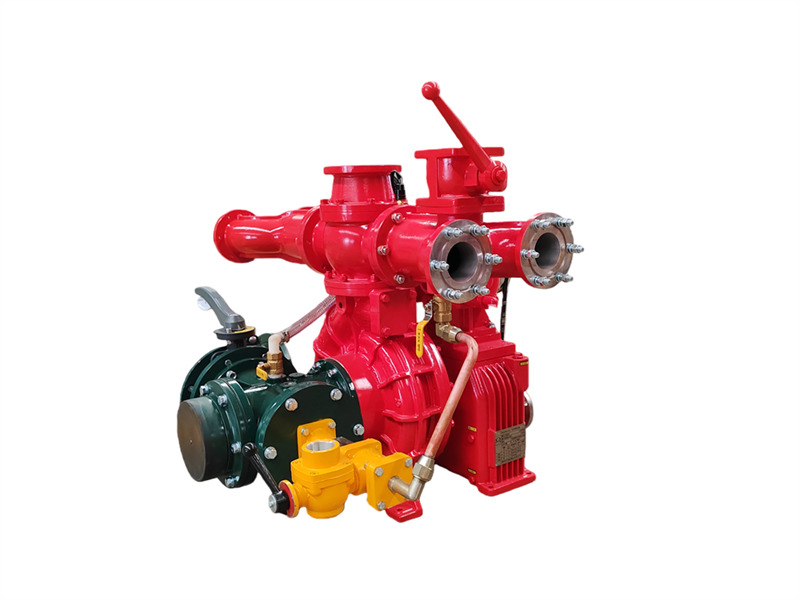
De CB10/60-RS op een vrachtwagen gemonteerde brandbluspomp bestaat uit een eentraps lagedruk-centrifugaalpomp, een dubbelzuiger-vacuümpomp, een automatische elektromagnetische koppeling-uitschakelinrichting, een toerentalverhoger, een uitlaatleiding en afsluitklep, en een inlaatleiding. ♦ Hoofdstructuur en functie (1) Eentraps lagedruk-centrifugaalpomp: Samengesteld uit een pompdeksel, pomphuis, eerste-traps waaier en pompas, levert deze de nominale druk en het nominale debiet. (2) Toerentalverhoger: De toerentalverhoger van de CB10/60-RS voertuigbrandbluspomp heeft een conventionele verhogingsverhouding van 1.440. (3) Dubbelzuiger-vacuümpomp: Voornamelijk samengesteld uit een zuiger, pomphuis, pompas en excentrisch wiel. Het excentrische wiel is voorzien van een zuigergeleidestang en een stalen pomphuls. Inlaat- en uitlaatkleppen zijn aan beide uiteinden van de zuigerpomp geïnstalleerd. Wanneer de elektromagnetische koppeling aangrijpt, begint de zuigerpomp te werken. Tijdens de werking zorgt de excentrische beweging van het excentrische wiel ervoor dat de zuiger heen en weer beweegt, waardoor de lucht geleidelijk uit de pomp en leiding wordt verwijderd en zo de luchtkwaliteit wordt verbeterd. In de holte wordt een vacuüm gecreëerd om het doel van wateraanzuiging te bereiken. 1. Uitlaat-afsluitklep (4 stuks); 2. Linker en rechter uitlaatwaterleidingen; 3. Aansluiting voor koelretourwater van versnellingsbak; 4. Aansluiting voor drukmeter; 5. Uitlaat-terugslagklep; 6. Waterkanonflens; 7. Waterdrukschakelaar; 8. Aansluiting voor drukretourwaterkoeling van aftakas (PTO); 9. Flens van achterste watertank; 10. Kogelkraan van achterste watertank; 11. Versnellingsbak; 12. Elektromagnetische koppeling en bedrading; 13. Zuigervulpomp; 14. Aansluiting voor vacuümmeter; 15. Aansluiting voor vacuümaanzuiging; 16. Interface voor inlaatleiding; 17. Vierweg-inlaatleiding; 18. Aftapklep van waterpomp; 19. Drukretourwaterleiding voor koeling van versnellingsbak; 20. Drukinlaatwaterleiding voor koeling van versnellingsbak; 21. Oliepeilklep voor smering van versnellingsbak; 22. Koppelingsflens; 23. Aandrijfriem; 24. Schroefdraadaansluiting voor drukwater van schuimproportioner (niet beschikbaar op watertankwagens); 25. Interface voor schuimproportioner; 26. Aansluiting voor drukuitlaatwaterkoeling van aftakas (PTO); 27. CB10/60 voertuigbrandbluspomp; 28. Aansluiting voor drukuitlaatwaterkoeling van versnellingsbak; 29. Achterste vlinderklep voor inlaat (4) Lage druk wateruitlaatleiding en afsluitklep: Bestaat uit een terugslagklep voor de lage druk wateruitlaat, linker- en rechterwateruitlaatleidingen, vier wateruitlaatleidingen en vier afsluitkleppen voor de wateruitlaat. (5) Achteraan gemonteerde waterinlaatleiding: Bestaat uit een vierweg-inlaatleiding, een inlaatfilterscherm, een externe inlaataansluiting en aan beide zijden van de vierweg-inlaatleiding; de rechterzijde heeft een aansluiting voor het installeren van een schuimproportioner en de linke...
Details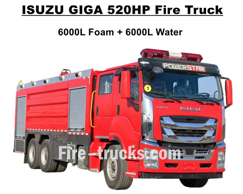
Topkwaliteit ISUZU GIGA brandweerwagens export naar West-Afrika Burkina Faso, ontworpen op basis van het ISUZU GIGA VC66 zware 6x4 vrachtwagenchassis, voorzien van de nieuwe GIGA VC66-cabine, standaard luchtgeveerde stoel en airconditioning voor comfortabel rijden. De truck is uitgerust met de Japanse ISUZU-technologie dieselmotor van het model 6WG1-TCG62, 520 pk en een cilinderinhoud van 15681 cc, gekoppeld aan een FAST handgeschakelde versnellingsbak met 12 versnellingen, zeer laag brandstofverbruik, standaard voorbanden 385/80R22.5 en achterbanden 315/80R22.5, in totaal 10+1 eenheden. De bovenbouwsets omvatten een watertank van 6000L en een schuimtank van 6000L, beide gemaakt van roestvrij staal #304-materiaal, duurzaam voor een lange levensduur. Uitgerust met een aangepaste zeer krachtige CB10/140-brandpomp met een effectief debiet van 140L/s, gekoppeld aan een dubbele brandmonitor boven op de tankopbouw, met model PL8/64 en een effectief debiet van 64L/s. Isuzu GIGA 520PK brandweerwagen uitgerust met alle noodzakelijke brandbestrijdingsapparatuur, een ideale brandweerwagen voor brandblussing en redding van mensen, en veel gebruikt op de markt van Burkina Faso. ISUZU GIGA 520PK 14.000L schuimtank-brandweerwagen CS TRUCKS-fabriek is een professionele fabrikant op het gebied van vrachtwagens,garandeert dat alle producten nieuw en van hoge kwaliteit zijn. Kenmerken van de ISUZU-brandweerwagen: Naam ISUZU GIGA 12000L schuimpomp-brandweerwagen Cabine GIGA VC66 Motor 6WG1-TCG62 met 520PK en 15681cc cilinderinhoud Versnellingsbak FAST 12 versnellingen Wielbasis 4600+1370mm Band Voor: 385/80R22.5 (2 stuks) Achter: 315/80R22.5 (8 stuks) Tank 6000L schuimtank (roestvrij staal #304) 6000L watertank (roestvrij staal #304) Brandpomp CB10/140 met debiet van 140L/s Brandmonitor Voorste: PL8/64 met debiet van 64L/s Achterste: PL8/64 met debiet van 64L/s Uitrusting Volledige sets brandbestrijdingsapparatuur volgens maatwerk Hoe bedient u de ISUZU-schuimtank-brandweerwagen: .
Details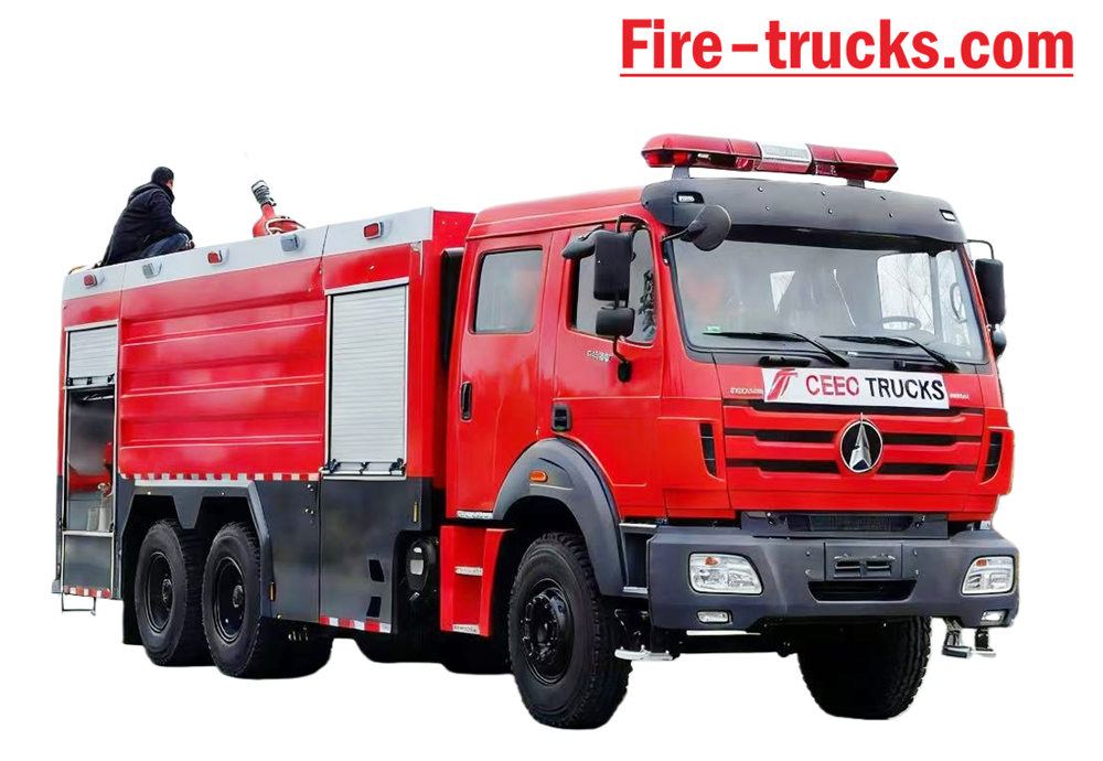
Beiben Brandweerwagen gebaseerd op het type II Beiben 2638 model 6x4 chassis met links stuur, carrosserie De capaciteit kan oplopen tot 12.000 liter, inclusief een watertank van 10.000 liter en een schuimtank van 2.000 liter. Beiben 2638 brandweer vrachtwagen Uitgerust met een XIONGZHEN CB10/60 brandbluspomp en een PL8/48 brandmonitor, zeer handig voor Dagelijks gebruik. Voornamelijk gebruikt voor brandbestrijdingsprojecten in alle gebieden waar dat nodig is. Het voertuig is ontworpen om volledig te profiteren van de voordelen van het originele Beiben-vrachtwagenchassis. Er is volledig rekening gehouden met het gebruiksgemak en de betrouwbaarheid van het product, evenals met het nieuw ontworpen chassis. De carrosserie Het materiaal is koolstofstaal van internationale standaard met een corrosiewerende coating en roestvrij staal, dat Kan effectief roestvorming voorkomen en een lange levensduur garanderen. De Beiben 6x4 brandweerwagen is uitgerust met een sandwich-PTO, brandweerpomp, brandmonitor, bemanningsruimte en brandslang. Box, pompkamer, droogpoedertankwagen en stikstofsysteem, gecombineerd met pijpslanghaspel, Engels versiebesturingskast, inlaat- en uitlaatleidingen, klimladder aan de achterzijde, bovenste kussenlamp en alle benodigde brandbestrijdingsapparatuur. Aangepaste dubbele cabine met 2+4 zitplaatsen voor een prettig rijgevoel. Daarom, de Dit voertuig is een ideale brandweerwagen, met name voor brandbestrijdingsprojecten. [if gte mso 9]> Normaal 0 7.8 磅 0 2 false false false EN-US ZH-CN X-NONE 1"/>
Details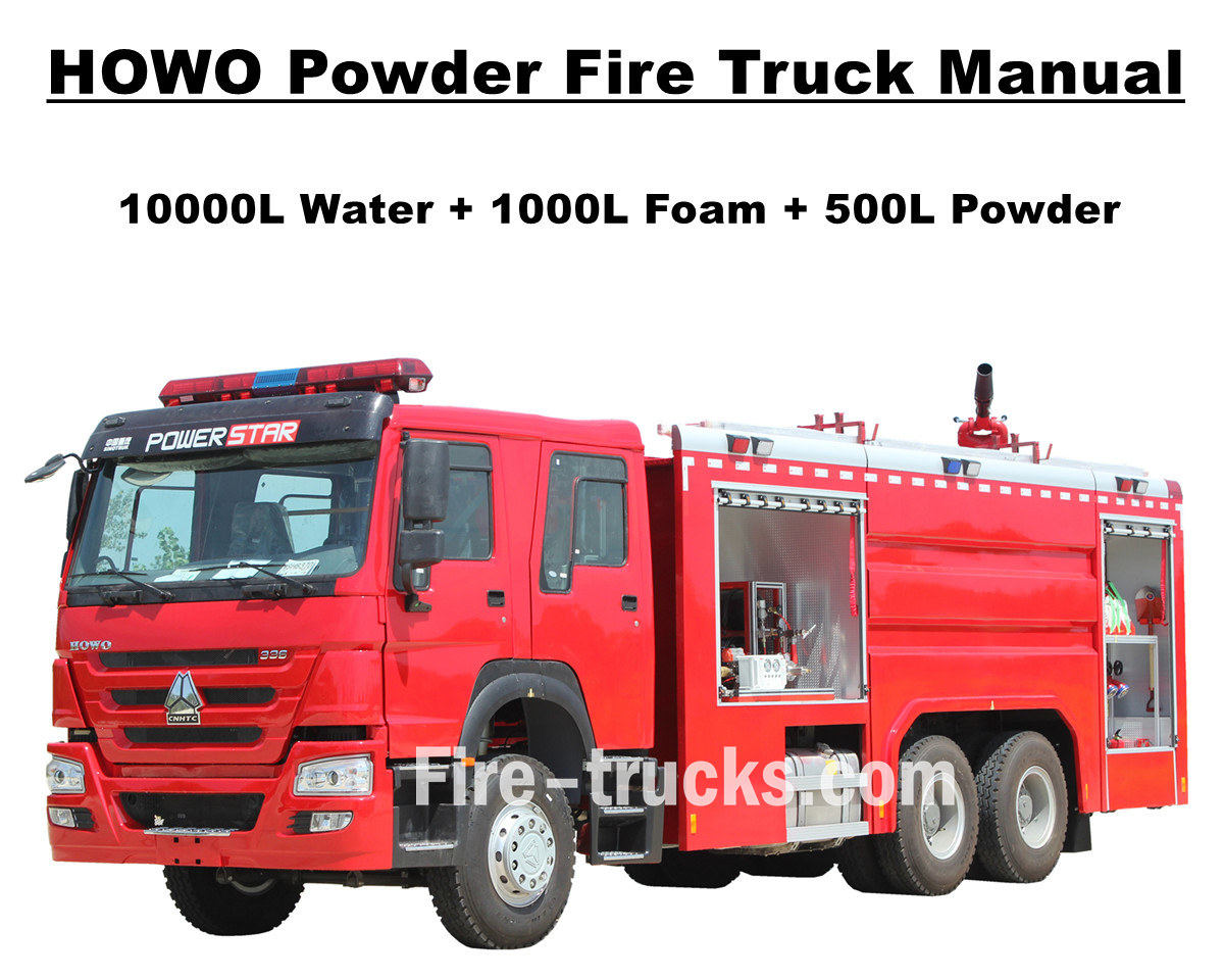
Een klant uit Afrika en Mauritanië kocht in totaal 4 eenheden. Sinotruk HOWO pompbrandweerwagen Deze brandweerwagen van POWERSTAR TRUCKS wordt gebruikt in de hoofdstad Nouakchott. Een brandweerwagen, ook wel brandweerauto of brandweerpomp genoemd, is een voertuig dat is ontworpen en geproduceerd om te voldoen aan de behoeften van diverse brandbestrijdings- en reddingsprojecten wereldwijd. De wagen is voorzien van een dubbele cabine voor de brandweerlieden en diverse brandbestrijdingsapparatuur en -gereedschappen voor brandbestrijding, reddingsoperaties, enz. Om de efficiëntie van de HOWO-brandweerwagens te garanderen, zijn ze uitgerust met ladders van aluminiumlegering, tanks voor water, schuim en droog blusmiddel, een efficiënte brandweerpomp CB10/60 met PL8/48 brandmonitor en een spuitbereik van meer dan 70 meter, een brandslanghaspel met spuitpistool voor brandbestrijding over lange afstand, ademhalingsapparatuur met masker, beschermende kleding, reddingsgereedschap, een EHBO-kit, enz. Al deze services voor de HOWO-brandweerwagens zorgen voor een efficiënte en betrouwbare werking. Om het gebruik van de HOWO-brandweerwagen voor Mauritaanse klanten zo eenvoudig en efficiënt mogelijk te maken, wordt elke wagen geleverd met een complete Engelstalige catalogus voor service, inclusief een gebruikershandleiding voor de bediening, een handleiding voor de wagen en een handleiding voor reserveonderdelen voor gebruik en onderhoud. SINOTRUK HOWO 14.000L poederbluswagen POWERSTAR-fabriek is een professionele fabrikant op het gebied van vrachtwagens. Wij garanderen dat alle producten gloednieuw en van hoge kwaliteit zijn. » I. Voordelen van de HOWO brandweerwagen: ★ Krachtige WEICHAI dieselmotor van 247 kW / 336 pk, 100.000 km probleemloos. ★ SINOTRUK HOWO klassieke HW76 cabine, Europees design ★ Gemonteerde CB10/60 brandweerpomp, debiet van 60 l/s, uiterst betrouwbaar ★ Bovenop gemonteerd PL8/48 waterkanon, duurzaam in gebruik ★ 500L droog poeder met stikstoffles, voorzien van luchtregelkleppen ★ Geïntegreerd besturingssysteem voor schuim en poeder, met bedieningspaneel aan de achterzijde. » II . Tekening van de brandweerwagen van Howo Rescue: [if gte mso 9]> Normaal 0 7.8 磅 0 2 false false false EN-US ZH-CN AR-SA Below are overview of the Africa Mauritania customer purchased Sinotruk HOWO dry powder fire engine. HOWO fire fighting truck for sale Left side view of HOWO fire engine Right side view of HOWO fire tanker truck » Ⅲ . HOWO fire truck factory production: After POWERSTAR Engineer Dept provide detailed fire truck drawing and confirmed with Mauritania customers, then we Production Department can start production process as schudule, mainly as below process: Classify main component of the Fire Rescue Equipment Start modify HOWO truck chassis Install mutilple fire equipment, including pump, monitor Install the dry powder system Factory do preshipment testing Start for shipment And Below showing the start of manufacturer, when HOWO Het 6x4 chassis met l...
Details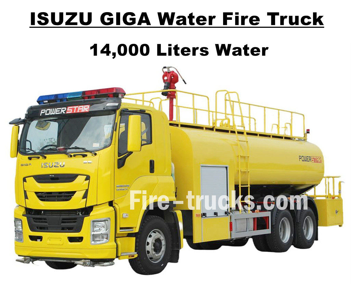
De Zuid-Amerikaanse klant, de heer Joseph uit Honduras, kocht één exemplaar. Isuzu GIGA VC66 14000L 3700 gallons waterbrandbestrijdingswagen van POWERSTAR TRUCKS, Dit voertuig is ontworpen op basis van het chassis van de Japanse ISUZU GIGA 6x4 zware vrachtwagen en is uitgerust met een 6UZ1-TCG60 dieselmotor met een vermogen van 280 kW / 380 pk. Deze 6-cilinder, 4-takt, watergekoelde, turbogeladen en intergekoelde motor heeft een efficiënte cilinderinhoud van 9839 ml en is gekoppeld aan een internationale standaard FAST 12-versnellingsbak met 12 versnellingen vooruit en 2 achteruit, wat het brandstofverbruik efficiënt reduceert. Het voertuig is voorzien van 13 stalen banden van het type 12R22.5, inclusief een reserveband, waardoor het zeer geschikt is voor diverse wegomstandigheden en bergachtig terrein. De wielbasis is naar keuze aan te passen met 4600 mm of 1370 mm. Een geschikte en handige oplossing voor brandbestrijdingsprojecten in meerdere ruimtes. De Isuzu GIGA 3700 gallons watertankwagen is volledig gebaseerd op Japanse technologie, waaronder het ISUZU-chassis en de originele GIGA VC66-cabine met airconditioning en verwarmings- en koelfunctie voor comfortabel rijden. De tankwagen is volledig vervaardigd uit roestvrij staal (SS304) en heeft een efficiënt volume van 14.000 liter (gelijk aan 3700 gallons). De tankwagen is uitgerust met een Chinese CB10/60 brandweerpomp en een PS8/50 brandmonitor bovenop, een complete set brandbestrijdings- en reddingsapparatuur en een op maat gemaakte citroengele laklaag. Dit alles maakt de GIGA een ideaal voertuig voor brandbestrijdingsprojecten in de straten en gemeenschappen van Honduras. De GIGA wordt geleverd met een complete Engelstalige servicecatalogus, inclusief een gebruikershandleiding, een handleiding voor het gebruik van de GIGA en een handleiding voor reserveonderdelen. Isuzu GIGA 14.000L waterpompbrandweerwagen POWERSTAR-fabriek is een professionele fabrikant op het gebied van vrachtwagens. Wij garanderen dat alle producten gloednieuw en van hoge kwaliteit zijn. » I. Voordelen van de Isuzu waterbrandweerwagen: ★ Krachtige 280 kW / 380 pk 6WG1 dieselmotor, 100.000 km probleemloos. ★ ISUZU VC66 met nieuwe GIGA-cabine, Europees design ★ Gemonteerde CB10/60 brandweerpomp, debiet van 60 l/s, uiterst betrouwbaar ★ Bovenop gemonteerd PS8/50 waterkanon, duurzaam en betrouwbaar ★ Geïntegreerd besturingssysteem, met bedieningspaneel aan de zijkant ★ Op maat gemaakte citroengele lak, glanzend en prachtig CB10/60 brandweerpomp Model : CB10/60 Druk : 1,0 MPa Maximale werkdruk : 1,232 MPa Stroomsnelheid : 60 l/s bij 1,0 MPa, snelheid 3286 ± 50 tpm, vermogen 102 kW, zuigdiepte 3 m 42 l/s bij 1,3 MPa, snelheid 3519 ± 50 tpm, vermogen 106 kW, zuigdiepte 3 m 30 l/s bij 1,0 MPa, snelheid 3120 ± 50 tpm, vermogen 73 kW, zuigdiepte 7 m Snelheidsverhouding : 1:1.44 PS8/50 Brandmonitor Model : PS8/50 Druk : 0,8 MPa Werkbereik : Water ≥ 65 M Verticale rotatie : -45° ~ +70° Horizontale rotatie : 0° ~ 360° Stroomsnelheid...
Details
Powerstar Trucks produceert op maat gemaakte hulpvervoertuigen en Brandweerwagens Powerstar Trucks Emergency Response heeft zich in de loop der jaren gevestigd als toonaangevende fabrikant van complete assortimenten op maat gemaakte brandweerwagens met expertise in Schuimwaterbrandweerwagens En reddingsvoertuig brandweerwagen Voortbouwend op de vertrouwde reputatie van brandweerlieden, levert Powerstar trucks flexibele, strategische en gespecialiseerde oplossingen die aansluiten op de unieke behoeften van elke brandweer, waarbij de hulpverleners centraal staan. 120 stuks reddingsbrandweerwagens voor levering 65 brandweerwagens voor reddingsoperaties worden geëxporteerd naar de politie van Oeganda. Brandweerwagens met watertank Schuimbrandbestrijdingsvoertuig Brandweerwagens worden hoofdzakelijk in vier categorieën ingedeeld op basis van hun functie: bluswagens, ladderwagens, speciale brandweerwagens en logistieke ondersteuningswagens. 01, Brandweerwagens zijn de belangrijkste krachten voor het direct blussen van branden, waaronder: * **Brandweerwagens met watertank:** Uitgerust met een eigen watertank en pomp, geschikt voor het blussen van algemene branden. * **Schuimbrandweerwagens:** Speciaal ontworpen voor het blussen van branden met brandbare vloeistoffen zoals olie. * **Droogpoederbrandweerwagens:** Geschikt voor het blussen van gas- en elektrische branden. * **Koolstofdioxidebrandweerwagens:** Worden gebruikt om waardevolle apparatuur en precisie-instrumenten te beschermen. * **Bluswagens voor gecombineerd gebruik van schuim en droog poeder:** Kunnen beide blusmiddelen tegelijkertijd gebruiken, met een breed scala aan toepassingen. 02, Brandweerwagens met hoogwerker worden gebruikt voor reddings- en brandbestrijdingsdoeleinden in hoge gebouwen, met name in: Brandweerwagens met ladder: Uitgerust met een telescopische ladder, waarmee mensen gered kunnen worden en branden op hoogte geblust kunnen worden. * **Brandweerwagens met sproeifunctie vanuit de lucht:** Gebruiken een op afstand bediende sproeiboom om blusmiddelen over lange afstanden te spuiten. * **Brandweerwagens met hoogwerker:** Deze zijn voorzien van een hydraulisch hefplatform voor reddings- en brandbestrijdingsdoeleinden. Toepassing van een brandweerwagen 03. Gespecialiseerde brandweerwagens zijn verantwoordelijk voor specifieke taken, zoals: * **Brandweerwagens voor reddings- en rampenbestrijding:** Uitgerust met sloopgereedschap en hijsapparatuur, gebruikt voor reddingsoperaties bij ongevallen. * **Verlichting brandweerwagens:** Zorgt voor krachtige verlichting voor reddingsoperaties 's nachts. * **Brandweerwagens voor rookafzuiging:** Worden gebruikt voor rookafzuiging bij ondergrondse branden. 04. **Logistieke ondersteuningsbrandweerwagens:** Deze bieden voornamelijk logistieke ondersteuning aan de brandlocatie, zoals: * **Watervoorziening voor brandweerwagens:** Zorgen voor een continue watervoorziening voor brandweerwagens aan het front. **Brandweerwagens:** Vervoer en aanv...
Details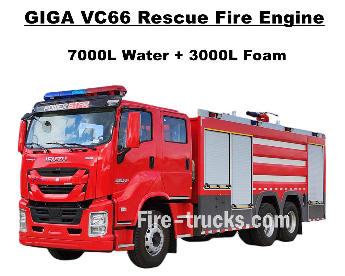
Klanten in Manila, Filipijnen, kochten Isuzu GIGA VC66 zware brandweerwagen van POWERSTAR TRUCKS, Deze is uitgerust met een Japanse ISUZU dieselmotor 6WG1-TCG61 met een vermogen van 338 kW / 460 pk. Het betreft een 6-cilinder, 4-takt, watergekoelde, turbogeladen en intergekoelde motor met een standaard cilinderinhoud van 15681 cc. Deze is gekoppeld aan een internationale standaard FAST 12-versnellingsbak met handgeschakelde transmissie (12 versnellingen vooruit en 2 achteruit), wat resulteert in een zeer laag brandstofverbruik. De auto is voorzien van 13 tubeless banden in de maat 315/80R22.5, inclusief een reserveband, waardoor hij zeer geschikt is voor diverse wegomstandigheden. Deze truck is geschikt voor brandbestrijdingsprojecten in diverse gebieden. De truck is volledig gebouwd op het originele ISUZU GIGA VC66 chassis en voorzien van een aangepaste GIGA dubbele cabine met 2+1 normale zitplaatsen voorin en 4 SCBA-zitplaatsen achterin. De cabine is uitgerust met airconditioning met verwarmings- en koelfunctie voor comfortabel rijden. De truck heeft een volledig roestvrijstalen (SS304) tankopbouw en is uitgerust met een hoogwaardige Chinese XIONGZHEN CB10/60 brandweerpomp in de pompkamer achterin, in combinatie met een WESTER PL8/48 brandmonitor bovenop de tankopbouw. De complete set brandbestrijdings- en reddingsapparatuur maakt deze truck een ideaal voertuig voor brandbestrijdingsprojecten in de straten en wijken van Manilla. De truck wordt geleverd met een complete Engelstalige servicecatalogus, inclusief een gebruikershandleiding, een handleiding voor het gebruik van de GIGA-truck en een handleiding voor reserveonderdelen. Isuzu brandweerwagen met 7.000 liter water en 3.000 liter schuim. POWERSTAR-fabriek is een professionele fabrikant op het gebied van vrachtwagens. Wij garanderen dat alle producten gloednieuw en van hoge kwaliteit zijn. » I. Belangrijkste kenmerken van de Isuzu 6WG1 brandweerwagen: ★ Krachtige 338 kW / 460 pk 6WG1 dieselmotor, 100.000 km probleemloos. ★ ISUZU VC66 met nieuwe GIGA-cabine, Europees design ★ Cabine met dubbele zitrij, met 4 SCBA-zitplaatsen achterin ★ Gemonteerde CB10/60-XZ brandbluspomp, debiet van 60 l/s, uiterst betrouwbaar ★ Bovenop gemonteerd PL8/48 schuimkanon, duurzaam in gebruik ★ Geïntegreerd besturingssysteem, met bedieningspaneel aan de achterzijde CB10/60-XZ brandweerpomp Model : CB10/60-XZ Druk : 1,0 MPa Maximale werkdruk : 1,232 MPa Stroomsnelheid : 60 l/s bij 1,0 MPa, snelheid 3286 ± 50 tpm, vermogen 102 kW, zuigdiepte 3 m 42 l/s bij 1,3 MPa, snelheid 3519 ± 50 tpm, vermogen 106 kW, zuigdiepte 3 m 30 l/s bij 1,0 MPa, snelheid 3120 ± 50 tpm, vermogen 73 kW, zuigdiepte 7 m Snelheidsverhouding : 1:1.44 PL8/48 Brandmonitor Model : PL8/48 Druk : 0,8 MPa Werkbereik : Schuim ≥ 70m en water ≥ 60m Verticale rotatie : -45° ~ +70° Horizontale rotatie : 0° ~ 360° Stroomsnelheid : 48 L/s » II . Technische tekening van de Isuzu brandweerwagen: De ISUZU GIGA VC66 brandweerwagen, uitgerust met een water- en ...
Details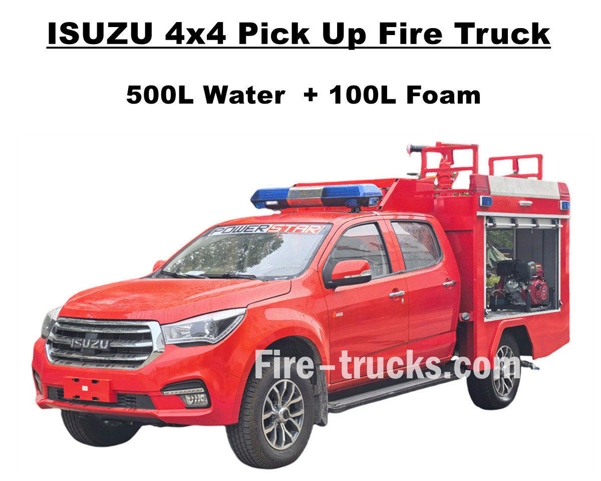
Fabrieksverkoop ISUZU 4x4 offroad pick-up brandweerwagen De Isuzu TAGA brandweerwagen met vierwielaandrijving is uitgerust met een uitstekend aandrijfsysteem dat alle soorten uitdagende wegen aankan. De Isuzu pick-up brandweerwagen heeft een volledig roestvrijstalen (SS304) tankopbouw, inclusief een watertank van 500 liter en een schuimtank van 100 liter, en een professionele, onafhankelijke brandweerpomp JBQ4.5/9 die achterin de pompkamer is gemonteerd. Deze pomp heeft een groot sproeibereik en een optioneel bedieningspaneel met meerdere talen. Er zijn diverse optionele configuraties beschikbaar om aan verschillende behoeften te voldoen, en bovenop is een PS20 brandmonitor voor waterstralen gemonteerd. Deze Isuzu pick-up brandweerwagen met 143 pk biedt een solide garantie voor brandveiligheid en demonstreert uitstekende prestaties en flexibiliteit. De originele dubbele cabine van de Isuzu brandweerwagen biedt voldoende ruimte en comfort voor het laden van brandbestrijdingsmateriaal en zorgt voor goede rijeigenschappen. De cabine biedt plaats aan 5 brandweerlieden en is voorzien van airconditioning, zodat de chauffeur in alle weersomstandigheden comfortabel kan blijven. Dit alles garandeert dat de ISUZU 600L schuimbrandweerwagen een ideaal brandweervoertuig is voor de Albanese markt. De onderstaande gebruikershandleiding is bedoeld voor een veilige bediening en gebruik. » I. Belangrijkste kenmerken van de Isuzu pick-up brandweerwagen: ★ Krachtige 4KH1-motor van 105 kW / 143 pk, 100.000 km probleemloos. ★ ISUZU TAGA nieuwe pick-up cabine, Europees design ★ Originele dubbele cabine, geschikt voor 5 brandweerlieden ★ Onafhankelijke JBQ4.5/9 brandweerpomp, superbetrouwbaar ★ Bovenop gemonteerd PS8/20-vuurkanon, duurzaam gebruik » II. Overzicht van de pick-upbrandweerwagen: De ISUZU 4x4 offroad AWD water- en schuimbrandweerwagen is een terreinwagen die ingezet kan worden in diverse omgevingen, zoals woonwijken, bossen en fabrieken. Dankzij zijn offroad-capaciteiten en compacte formaat kan deze Isuzu pick-up brandweerwagen meerdere missies succesvol uitvoeren. Om onze brandweerwagens nog beter af te stemmen op de behoeften van verschillende klanten, bieden we hieronder verschillende opties aan. ----- Tankermateriaal : Koolstofstaal, roestvrij staal, aluminiumlegering, PP-materiaal ----- Brandweerpomp : Afhankelijk van de romp van de tanker en de afstand die de tanker aflegt, is er een optionele Amerikaanse optie. Darley merk ----- Optioneel: Pijpleiding, slanghaspel, aluminium ladder, gecombineerd model (Chinees, Europees, Amerikaans type) » III. Aantrekkelijk uiterlijk: De Isuzu 4x4 AWD pick-up brandweerwagen is krachtig en wendbaar, kan snel ter plaatse zijn bij een brand en rijdt gemakkelijk door complex terrein. Het waterkanon bovenop heeft een groot bereik en een hoge waterdruk, en de 50 meter lange brandslanghaspel met pistool kan de brandhaard nauwkeurig raken en efficiënt afdekken en isoleren. De pick-up brandweerwagen is bovendien uitgerust me...
Details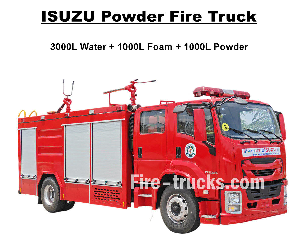
Nieuw ontworpen en geproduceerd ISUZU GIGA 4X bluswagen met waterschuim en droog poeder Dit is een krachtige Isuzu brandweerwagen die geëxporteerd wordt naar Lagos, Nigeria. Hij is uitgerust met een 4HK1-TCG60 dieselmotor met een vermogen van 150 kW/205 pk en een cilinderinhoud van 5193 cc. Deze motor is gekoppeld aan een MLD handgeschakelde zesversnellingsbak met 6 versnellingen vooruit en 1 achteruit. Dit zorgt voor een efficiënte vermogensafgifte en een laag brandstofverbruik, wat tevens een snelle respons en stabiele rijeigenschappen garandeert. De Isuzu 5000L brandweerwagen is voorzien van een complete tankopbouw van 5000 liter, bestaande uit een watertank van 3000 liter, een schuimtank van 1000 liter en een poedertank van 1000 liter. Alle tanks zijn vervaardigd van roestvrij staal SS304, hebben een vierkante vorm met schotten aan de binnenzijde en zijn voorzien van een DN500 mangatdeksel met slot voor extra veiligheid. De Isuzu poederbrandweerwagens zijn uitgerust met een CB10/40 brandweerpomp met een efficiënte doorstroomsnelheid van 40 l/s, gekoppeld aan een PL8/32 water-schuimbrandblussysteem met een efficiënte doorstroomsnelheid van 32 l/s. In combinatie met diverse reddingsmiddelen maakt dit de Isuzu Giga 4X brandweerwagen een ideaal voertuig voor brandbestrijding en reddingsoperaties, en zeer effectief ingezet in Lagos, Nigeria. De truck is tevens uitgerust met een droogpoedertankwagen van het model R25-006, met een ontwerpdruk van 1,55 MPa en een ontwerpvolume van 1000 liter, en voorzien van stikstofflessen. Om de werking en prestaties van de Isuzu brandweerwagens te optimaliseren, is de onderstaande handleiding beschikbaar voor gebruik door klanten in Nigeria. ♦ ISUZU GIGA Droogpoederbrandweerwagen ♦ POWERSTAR ISUZU Droogpoeder Brandweerwagen Handleiding export Nigeria Bedieningspaneel van ISUZU brandweerwagens Gedetailleerde onderdelen van een Isuzu brandweerwagen » I. Belangrijkste kenmerken van de Isuzu brandweerwagen: ★ Krachtige 4HK1-motor met 205 pk, 100.000 km probleemloos. ★ ISUZU GIGA nieuw model 4X cabine, Europees design ★ ISUZU-technologie-as, uitermate geschikt voor Afrika. ★ De beroemde CB10/40-pomp uit China, superbetrouwbaar ★ Topklasse PL8/32 vuurkanon, duurzaam ★ Droogpoederassemblage, bijpassende stikstofflessen » II. ISUZU Brandweerwagenfabrikant: De ISUZU GIGA Water Foam Dry Powder Fire Fighting Truck is een volledig functionele middelgrote gevechtsbrandweerwagen die een hoge mobiliteit, ruime blusreserves en diverse gevechtsmogelijkheden combineert. Qua aandrijving is hij voorzien van een Weichai-motor in combinatie met een Sinotruk-transmissie, wat zorgt voor een krachtig vermogen en een efficiënte overbrenging. ----- Tankermateriaal : Koolstofstaal, roestvrij staal, aluminiumlegering, PP-materiaal ----- Brandweerpomp : Afhankelijk van de romp van de tanker en de afstand die de tanker aflegt, is er een optionele Amerikaanse optie. Darley merk ----- Optioneel: Pijpleiding, slanghaspel, aluminium ladder, gecombi...
Details
Moldavische klanten kochten 6 exemplaren. Isuzu GIGA 4X luchthavenbrandweerwagen van POWERSTAR TRUCKS, en service voor brandbestrijdingsprojecten in meerdere gebieden. Volledig gebaseerd op het originele ISUZU GIGA 4X vrachtwagenchassis, aangepast met een dubbele cabine met 2+1 normale zitplaatsen voorin en 4 SCBA-zitplaatsen achterin. De cabine is uitgerust met airconditioning met verwarmings- en koelfunctie voor comfortabel rijden. Uitgerust met een Japanse ISUZU dieselmotor 4HK1-TCG60 met een vermogen van 151 kW / 205 pk, een viercilinder, viertakt, watergekoelde, turbogeladen en intergekoelde motor met een standaard cilinderinhoud van 5193 cc, gekoppeld aan een ISUZU MLD handgeschakelde zesversnellingsbak (6 versnellingen vooruit en 1 versnelling achteruit), wat resulteert in een zeer laag brandstofverbruik. De auto is voorzien van zeven tubeless banden in de maat 295/80R22.5, zeer geschikt voor diverse wegomstandigheden. Isuzu brandweerwagen met 5000 liter water en 1000 liter schuim. POWERSTAR-fabriek is een professionele fabrikant op het gebied van vrachtwagens. Wij garanderen dat alle producten gloednieuw en van hoge kwaliteit zijn. » Ⅰ Brandbestrijdingstoepassingen: De ISUZU GIGA 4X is een nieuw ontworpen brandweerwagen met 205 pk, uitgerust met een complete set brandbestrijdingsapparatuur en reddingsmiddelen. Dankzij de efficiënte water- en schuimstraal met hoge sproeiafstand en -snelheid is deze wagen geschikt voor diverse brandbestrijdingswerkzaamheden in steden, fabrieken, woonwijken, enz. Gedetailleerde geavanceerde kenmerken vindt u hieronder: 1. ISUZU GIGA 4X Vrachtwagen: Japanse ISUZU 4HK1-TCG60 model met 151 kW / 205 pk dieselmotor 2. SS304 Materiaaltanker: Op maat gemaakte watertankwagen van 5000 liter en schuimtankwagen van 1000 liter, beide vervaardigd uit roestvrij staal SS304. 3. CB10/40 Brandweerpomp: Achteraan gemonteerd, met onafhankelijke ruimte, beschikbare pomp-in- en pompfunctie. CB10/40 brandweerpomp Model : CB10/40 Druk : 1,0 MPa Maximale werkdruk : 1,38 MPa Stroomsnelheid : 40 l/s bij 1,0 MPa, snelheid 3330 ± 50 tpm, vermogen 60 kW, zuigdiepte 3 m 28 l/s bij 1,3 MPa, snelheid 3540 ± 50 tpm, vermogen 59 kW, zuigdiepte 3 m 20 l/s bij 1,0 MPa, snelheid 3335 ± 50 tpm, vermogen 42 kW, zuigdiepte 7 m Snelheidsverhouding : 1:1.542 4. PL8/36 Brandmonitor: Bovenop gemonteerd, handmatig bedienbaar model met een sproeibereik van meer dan 55 meter, efficiënt en duurzaam. PL8/36 Brandmonitor Model : PL8/36 Druk : 0,8 MPa Werkbereik : Schuim ≥ 60m en water ≥ 48m Verticale rotatie : -45° ~ +70° Horizontale rotatie : 0° ~ 360° Stroomsnelheid : 36 l/s 5. Geïntegreerd Bedieningsapparaat ISUZU brandweerwagens uitgerust met een geïntegreerd bedieningspaneel in de pompkamer achterin, handig en slim. » II . Geavanceerde functies van de brandweerwagen: De ISUZU GIGA 4X zware brandweerwagen is een ideale brandweerwagen voor brandbestrijding en reddingsoperaties. Hij beschikt over geavanceerde ontwerpkenmerken en betrouwbare kwaliteit voor...
Details
Lees verder, blijf op de hoogte, abonneer je en laat ons vooral weten wat je ervan vindt.

 IPv6 Network ondersteund

 Nederlands
 English
 français
 Deutsch
 русский
 italiano
 español
 português
 العربية
 日本語
日本語 한국의
한국의 Türkçe
 Melayu
 ไทย
ไทย Tiếng Việt
 Indonesia
  中文
中文 қазақ
қазақ Filipino
 မြန်မာ
 српски