Laat Een Bericht Achter
Als u geïnteresseerd bent in onze producten en meer details wilt weten, laat dan hier een bericht achter. We nemen zo snel mogelijk contact met u op.

The fire truck PTO (Power Take-Off) is a power transmission device that transfers engine power to the fire pump. When the firefighter activates the PTO, mechanical power from the engine is transmitted through the transmission and PTO to the fire pump — this is the core working principle of how a fire fighting truck PTO system operates — enabling the pump to deliver high-pressure, high-flow water or foam without the need for a separate auxiliary engine.
Modern fire trucks typically use side-mounted PTO or full power PTO systems. These offer stable power output, convenient operation, and low maintenance costs, making them an essential component of the fire truck's firefighting system.
 Work")
PTO (Power Take-Off) is a critical component in the fire truck's power system. It is a gear transmission device installed between the engine and the transmission, designed to "divert" a portion of mechanical power from the vehicle's engine or transmission to the fire pump or other auxiliary equipment, without affecting the vehicle's normal driving capability.
The fire truck engine is originally responsible only for driving the wheels. However, once the fire truck arrives at the fire scene, the wheels no longer need power, while the fire pump requires power to draw and pressurize water. The PTO is the device that accomplishes this "power switch."

Power Take-Off (PTO) literally means "power output device."
On a fire truck, it refers to extracting rotational power from the engine flywheel or transmission gears through gear engagement, and delivering it to the fire pump or other auxiliary equipment.
Its name describes its function:
Engine = Power source
PTO = Power distributor
Fire pump = Power consumption end
Therefore, the PTO is the bridge connecting the "power source" and the "firefighting system."
The core reason fire trucks must be equipped with a PTO is that firefighting operations require continuous, stable, high-power output that cannot rely on the vehicle's driving state.
Main reasons:
1. Provides continuous firefighting power
The fire pump needs to run for extended periods during firefighting operations. The PTO allows the engine to continuously drive the fire pump at idle or fixed RPM, ensuring stable water pressure and flow.
2. Improves power utilization efficiency
Without a PTO, a separate auxiliary engine would be required to drive the fire pump, which would increase:
Cost
Maintenance complexity
Risk of failure
Space occupation
The PTO directly utilizes the vehicle's engine power, improving overall efficiency.
3. Supports multiple firefighting systems
Modern industrial fire trucks may include not only water pumps but also:
Foam systems
Dry powder systems
High-pressure water systems
Remote-controlled fire monitors
Without a PTO, there are only two solutions:
Install a separate engine to drive the pump → increases weight, cost, maintenance points, and occupies space
Keep the pump permanently connected to the transmission → pump stops when vehicle stops, unable to pump water on site
The PTO solves both problems at once:
| Mode | PTO Status | Power Destination | Result |
| Driving mode | Disengaged | All to wheels | Normal driving |
| Firefighting mode | Engaged | All to fire pump | Pumping while stationary |
The PTO is essentially a "power distribution and conversion system" that transforms vehicle driving power into firefighting operational power.
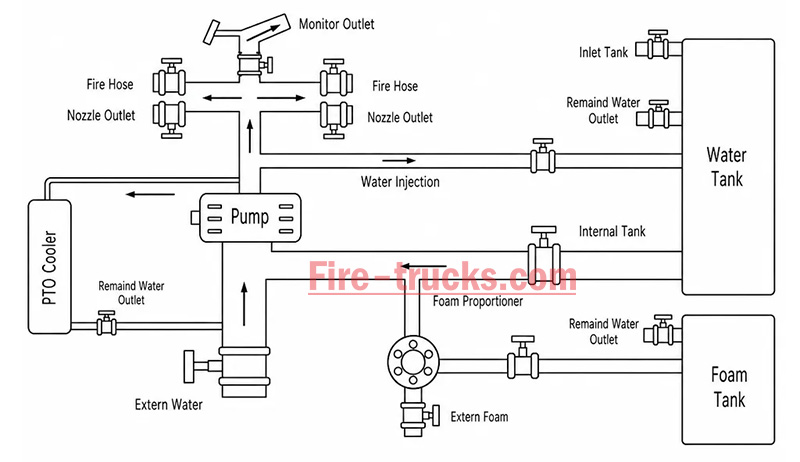
From an engineering perspective, the complete power path is:
Engine → Transmission → PTO → Drive Shaft → Fire Pump → Fire Monitor/Hose System
The PTO's working principle can be summarized in three key stages: power take-off, engagement, and transmission.
The PTO draws power from the engine. Depending on the installation position, the power take-off method differs:
| PTO Type | Installation Position | Power Source | Characteristics |
| Side-mounted PTO | Transmission side | Transmission countershaft gear | Simple structure, lower power (≤50% engine power) |
| Sandwich PTO | Between engine and transmission | Engine flywheel | Full power output, mainstream configuration |
| Split-shaft PTO | Between transmission and driveshaft | Transmission output shaft | High power, allows pumping while driving |
After the driver presses the PTO switch in the cab, the engagement mechanism activates:
| Engagement Method | Working Principle | Common On |
| Electric solenoid control | Electrical signal activates solenoid, pushing shift fork | Mainstream on modern fire trucks |
| Pneumatic control | Compressed air pushes piston, actuating fork | Large fire trucks |
| Manual cable | Mechanical cable directly pulls fork | Older vehicles |
Operation sequence:
Press PTO switch → Solenoid/cylinder actuates → Shift fork pushes sliding gear → Meshes with flywheel or transmission gear → Power connected
After the PTO output shaft begins rotating, power is transmitted through the drive shaft to the fire pump:
PTO output shaft rotates → Drive shaft → Fire pump input shaft → Pump impeller rotates → Water is pressurized and discharged
| Step | Action | Result |
|---|---|---|
| Step 1 | Engine starts, vehicle idling or driving | Engine running, PTO disengaged |
| Step 2 | Arrive at scene, driver presses PTO switch | Driving power disengaged (on some models), PTO gear activated |
| Step 3 | PTO establishes power connection with transmission | Transmission power is diverted to PTO output shaft |
| Step 4 | Drive shaft transmits power to fire pump | Fire pump begins receiving continuous mechanical power |
| Step 5 | Fire pump impeller rotates at high speed | Suction → Pressurization → Delivery to discharge lines → Firefighting |
| Step 6 | System reaches balanced RPM | Stable output, adjustable pressure, flow, and spray pattern |
The fire truck PTO system is a complete power transmission chain, with multiple components working together to transfer engine power to the fire pump. The system can be broken down into six core components:
The engine is the power source of the PTO system and the heart of the entire fire truck.
Function: Generates raw rotational power, driving the flywheel or crankshaft.
Power output: Typically 300–600 HP (depending on chassis model and configuration).
Relationship with PTO: The PTO draws power from the engine flywheel or crankshaft — it is the starting point of power.
Key characteristic: Engine RPM directly affects PTO output speed and the fire pump's water discharge capability. Fire trucks are typically equipped with high-power diesel engines, which not only drive the vehicle but also provide ample power reserve for the fire pump. After PTO engagement, the operator can control pump discharge pressure by adjusting engine RPM.
The transmission is responsible for power delivery and speed matching.
Function: Receives engine power and adjusts speed and torque through different gear combinations.
Relationship with PTO: Side-mounted PTO draws power from internal transmission gears; sandwich PTO is installed at the front of the transmission.
Key characteristic: Transmission gear position does not affect PTO output speed — PTO operates independently of gear selection.
Two power take-off positions:
Transmission side window take-off: PTO mounted on transmission side, drawing power from countershaft or intermediate shaft gears; common on medium-duty fire trucks.
Transmission rear-end take-off (sandwich): PTO installed between engine and transmission, drawing power directly from the flywheel, enabling full power output.
The PTO is the core of the entire system, responsible for "extracting" power from the engine and delivering it to the fire pump.
Function: Extracts power from the engine or transmission and converts it to the speed and torque suitable for the fire pump.
Installation position: Transmission side (side-mounted) or between engine and transmission (sandwich).
Key characteristic: Determines power transmission efficiency, speed matching, and operational convenience.
The drive shaft is the "power bridge" connecting the PTO and the fire pump.
Function: Transmits rotational power from the PTO output shaft to the fire pump input.
Structure: Typically consists of a metal shaft tube, universal joints, and splined connections.
Key characteristic: Must be precisely aligned to avoid vibration; universal joints allow angular compensation.
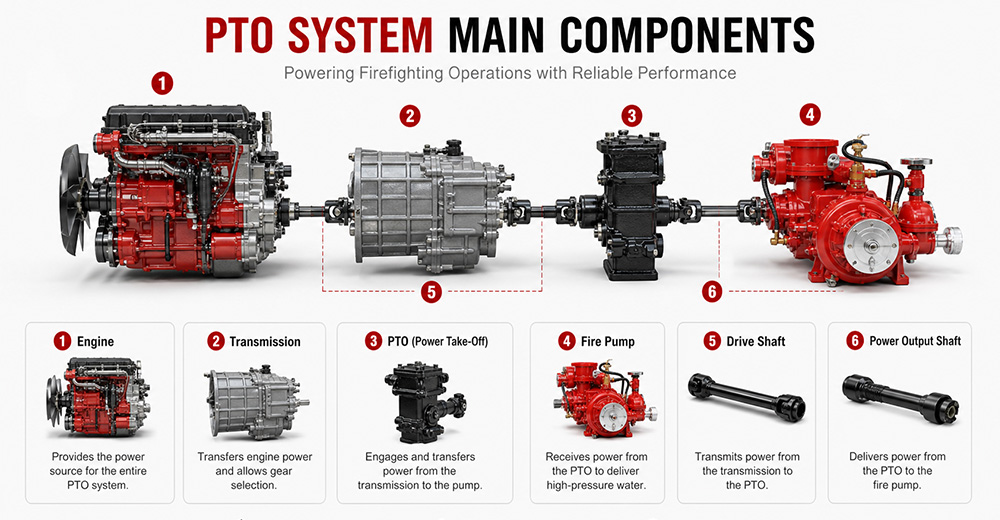
The fire pump is the final load of the PTO system, responsible for converting mechanical energy into water pressure energy.
Function: Receives rotational power from the PTO, drives the impeller to rotate, draws water in, and discharges it under high pressure.
Type: Centrifugal pump (single-stage, two-stage, or multi-stage).
Typical flow rate: 20 L/s – 180 L/s (1,200 – 6,000 L/min).
Typical pressure: 1.0 – 2.5 MPa (10 – 25 bar).
The PTO control system is the "command center" between the driver and the PTO system, responsible for engagement, disengagement, safety protection, and status indication.
Function: Controls PTO engagement and disengagement, monitors system status, and provides safety protection.
Operating location: Cab interior (primary control) and pump panel (auxiliary control).
Control methods: Manual cable, electric solenoid, pneumatic.
Specific control functions:
(1) PTO Engagement Control
The operator presses the PTO switch (electric solenoid/pneumatic) or pulls the lever (manual) in the cab. The control system sends a signal to engage the PTO's internal gears with the power source. After successful engagement is confirmed, an indicator light illuminates, allowing the operator to increase engine RPM.
(2) PTO Disengagement Control
The operator presses the switch again or resets the lever. The control system cuts the signal, and the PTO gears disengage. After disengagement is confirmed, the indicator light turns off.
| PTO Type | Installation Position | Power Source | Power Output | Typical Application |
| Sandwich PTO | Between engine and transmission | Engine flywheel | Full power (≥90%) | Fire pumpers, aerial trucks |
| Split-shaft PTO | Middle of chassis driveshaft | Transmission output shaft | Full power | Large vacuum trucks, airport fire trucks |
| Side-mounted PTO | Transmission side | Transmission gears | Partial power (lower) | Sprinkler trucks, small vacuum trucks |
Sandwich PTO
Advantages: Full power output (≥90%), supports "pumping while driving" (dual-function), high transmission efficiency, easy lubrication.
Disadvantages: Higher cost, complex installation, requires modification to the engine-transmission connection.
Split-shaft PTO
Advantages: Full power output, no additional space required, high reliability, good dynamic balance, can replace auxiliary engine to drive large pumps.
Disadvantages: Requires cutting the original driveshaft, installation position selection must consider driveshaft angle and length compensation.
Side-mounted PTO
Advantages: Low cost, simple installation, can draw power directly from the transmission side.
Disadvantages: Only partial power available, lower output torque, cannot drive high-power fire pumps, mainly used for low-speed, low-power equipment.
 for Fire Trucks")
The process follows a clear mechanical transmission chain:
Engine → PTO → Drive Shaft → Fire Pump → Impeller Rotation → Suction → Pressurization → Fire Monitor
| Factor | Role |
|---|---|
| Centrifugal pump characteristic | When impeller speed is constant, discharge pressure remains naturally stable |
| PTO rigid connection | No slippage or power loss, ensuring continuous stable power input |
| Pressure governor | Automatically detects flow changes and adjusts engine RPM to maintain set pressure |
| Relief valve | Automatically bypasses when pressure exceeds limit, preventing equipment damage |
① Pump speed is determined by engine RPM
Fire pump impeller speed = Engine RPM × PTO ratio. The PTO ratio is fixed (e.g., 1.75:1), so pump speed changes directly with engine RPM.
Calculation formula:
Engine RPM × PTO ratio = Pump speed (RPM)
② Physical relationship between pressure and speed
The pressure generated by a centrifugal pump is proportional to the square of the impeller speed. This physical law means that small changes in RPM cause significant pressure fluctuations.
Speed increases → Centrifugal force increases → Discharge pressure rises
Speed decreases → Centrifugal force decreases → Discharge pressure drops

1. PTO will not engage
Possible causes: Low air pressure (pneumatic type), faulty solenoid, damaged or stuck cable, interlock conditions not met (parking brake not applied, transmission not in neutral).
Solutions: Check air system pressure (must be ≥0.6 MPa); test solenoid; inspect cable; confirm parking brake is applied and transmission is in neutral.
2. PTO engages but pump does not work
Possible causes: PTO clutch failure, broken drive shaft or worn splines, damaged internal gears.
Solutions: Check PTO clutch engagement; inspect drive shaft for breakage or loose connections; disassemble and inspect internal gears.
3. PTO unusual noise
Possible causes: Poor gear meshing or wear, worn bearings, insufficient or degraded lubrication, PTO not fully disengaged.
Solutions: Check gear clearance and tooth wear; inspect bearings; replace with qualified lubricant; confirm PTO is fully disengaged.
4. PTO oil leakage
Possible causes: Worn or deteriorated seals, cracked housing, loose mounting bolts.
Solutions: Replace seals (O-rings, oil seals); inspect housing for cracks; tighten mounting bolts.
5. PTO overheating
Possible causes: Prolonged high-load operation, insufficient or degraded lubricating oil, cooling system failure.
Solutions: Reduce load or shut down for cooling; replace with qualified lubricant; inspect cooling lines.
6. PTO insufficient power
Possible causes: Improper PTO ratio selection, engine RPM set too low, clutch slippage.
Solutions: Confirm PTO ratio matches the fire pump; increase engine RPM to rated operating range; inspect clutch for slippage.
Q1. What does PTO stand for on a fire truck?
PTO stands for Power Take-Off. It is a mechanical system that transfers engine power from the truck's transmission to the fire pump. In simple terms, PTO allows the fire truck's engine to power the pumping system so it can deliver high-pressure water or foam for firefighting operations without needing a separate engine. It is a critical component in industrial and municipal fire trucks.
Q2. Why do fire trucks need a PTO?
Fire trucks need a PTO because it enables the vehicle's main engine to drive the fire pump efficiently. Without a PTO, the fire pump would require a separate engine, which increases cost, weight, and maintenance complexity. PTO systems provide a compact, reliable, and fuel-efficient way to ensure continuous water or foam supply during firefighting operations.
Q3. Can a fire truck operate without a PTO?
Most modern fire trucks cannot operate their pumping system without a PTO because the PTO is responsible for transferring engine power to the fire pump. However, some specialized fire vehicles may use an independent auxiliary engine to drive the pump. These designs are less common due to higher cost, increased maintenance, and lower efficiency compared to PTO-based systems.
Q4. What is the difference between PTO and a fire pump?
The PTO is a power transmission device, while the fire pump is a water or foam pumping system. The PTO delivers mechanical power from the engine to the pump, and the fire pump converts that power into hydraulic pressure to move water or foam. In short, PTO is the "power source connector," and the fire pump is the "firefighting output device."
Q5. How much power can a fire truck PTO provide?
The power output of a fire truck PTO depends on the vehicle design and transmission system. Typically, PTO systems can provide between 50 kW to over 300 kW of mechanical power. Heavy-duty industrial and airport fire trucks often use high-capacity PTO systems capable of supporting large-flow fire pumps and continuous high-pressure operations.
Q6. What are the different types of fire truck PTOs?
There are several types of fire truck PTO systems, including side-mounted PTO, rear-mounted PTO, split shaft PTO, and full power PTO. Side-mounted PTO is commonly used in standard fire trucks, while split shaft and full power PTO systems are used in industrial and airport fire trucks where higher power output and continuous operation are required.
Q7. How do you maintain a fire truck PTO?
PTO maintenance includes regular inspection of lubrication oil levels, checking for leaks, tightening mounting bolts, and ensuring proper alignment of the drive shaft. Operators should also test engagement and disengagement functions regularly. Preventive maintenance is essential to avoid overheating, mechanical wear, and unexpected failure during emergency operations.
Q8. What causes a fire truck PTO to fail?
Common causes of PTO failure include insufficient lubrication, worn gears, misalignment of the drive shaft, overheating, and improper operation by the driver. Electrical or hydraulic control system failures can also prevent PTO engagement. Regular maintenance and correct operating procedures significantly reduce the risk of PTO failure.
Q9. Which PTO is best for industrial fire trucks?
For industrial fire trucks, the best option is usually a split shaft PTO or full power PTO system. These systems can handle high power output, continuous operation, and large-capacity fire pumps. They are widely used in petrochemical plants, refineries, airports, and large industrial facilities where reliable and long-duration firefighting performance is required.
Q10. What should buyers consider when choosing a fire truck PTO?
Buyers should consider engine power compatibility, required fire pump flow rate, vehicle type, and working environment. It is also important to evaluate PTO durability, cooling performance, maintenance accessibility, and compatibility with the chassis. For export projects, compliance with international standards and local regulations should also be taken into account to ensure approval and operational reliability.
PTO (Power Take-Off) is the core system that transfers engine power to the fire pump — it determines whether the entire firefighting system can operate properly.
The fire truck power chain is: Engine → Transmission → PTO → Drive Shaft → Fire Pump → Fire Monitor. Any weak link in this chain affects final firefighting performance.
The primary function of the PTO is to provide stable, continuous mechanical power output, enabling the fire truck to deliver efficient water or foam supply without requiring a separate engine.
Different PTO types (Side-mounted, Rear-mounted, Split shaft, Full power) are suited to different fire truck classes. Industrial fire trucks typically prioritize high-power PTO systems.
PTO performance must match the fire pump flow rate and vehicle chassis, otherwise issues such as insufficient power, unstable pressure, or system overload may occur.
Regular PTO system maintenance (lubrication, tightening, alignment inspection) is key to ensuring reliable fire truck operation, especially in high-intensity industrial applications.
When purchasing industrial fire trucks, buyers should not focus solely on price. PTO power, stability, compatibility, and after-sales support are equally critical factors to evaluate.
For high-risk scenarios such as petrochemical plants, airports, and large industrial parks, Full Power PTO or Split Shaft PTO systems are recommended to ensure continuous operational capability.


U bent misschien geïnteresseerd in de volgende informatie
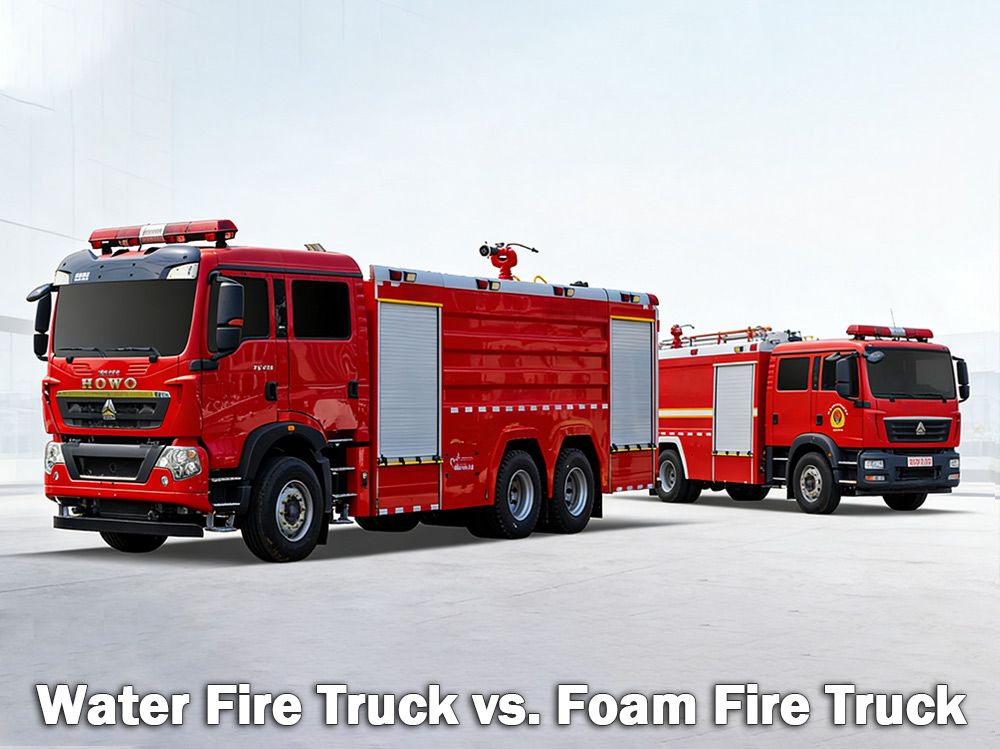
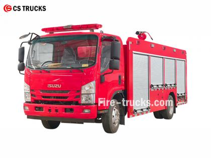
Brandweerwagens met watertank Brandweerwagens met schuimblussers bestrijden gewone branden van hout, papier en textiel. Schuimbluswagens bestrijden branden van brandbare vloeistoffen zoals benzine en olie. Welke wagen het meest geschikt is, hangt af van de aanwezige gevaren. A brandweerwagen met watertank Het voertuig heeft een grote watertank en gebruikt een hogedrukpomp om water via slangen of een waterkanon te leveren. Het is het meest voorkomende type brandweerwagen dat wereldwijd door gemeentelijke brandweerkorpsen en industriële bedrijven wordt gebruikt. A schuimbrandweerwagen Een ander type blusvoertuig is speciaal ontworpen voor het vervoeren en afgeven van blusschuim. Wanneer water alleen een brand niet effectief kan blussen – bijvoorbeeld bij brandbare vloeistoffen, chemicaliën of brandstoffen – is schuim de betere keuze. Schuim werkt door een deken over de brand te vormen, waardoor de zuurstoftoevoer wordt afgesneden en herontsteking wordt voorkomen. I. Wat is een waterbrandweerwagen? Een waterbrandweerwagen is precies wat de naam al zegt: een voertuig uitgerust met een grote watertank, een krachtige pomp en slangen of sproeiers om water op branden te spuiten. De watertank heeft doorgaans een inhoud van 500 tot 3.000 gallon (ongeveer 2.000 tot 12.000 liter). De pomp zuigt water aan uit de tank of uit een externe bron, zoals een brandkraan, meer of vijver, en perst het vervolgens onder hoge druk door de slangen. Waar waterbrandweerwagens het beste presteren: Waterbrandweerwagens zijn ideaal voor Branden van klasse A , waarbij gewone brandstoffen betrokken zijn: Hout en timmerhout Papier en karton Doek en stof Rubber en kunststoffen Gras, struikgewas en bosmateriaal Als het vuur brandbare materialen betreft in een huis, magazijn of op een veld, kan het meestal met water geblust worden. Beperkingen van water: Water heeft één groot nadeel. Wanneer het op brandende vloeistoffen zoals benzine, olie of chemicaliën wordt gespoten, zinkt het water omdat het zwaarder is dan deze brandstoffen. De brandstof blijft erboven drijven en brandt verder. In sommige gevallen kan water het vuur zelfs over een groter gebied verspreiden. Daarom is water alleen niet effectief bij branden van brandbare vloeistoffen. Specificaties van de waterpomp voor brandweerwagens: Brandweerwagen met watertank brandmonitor specificaties: II. Wat is een schuimbluswagen? Een schuimbluswagen is een gespecialiseerd voertuig dat is ontworpen voor het transporteren en toedienen van blusschuim. Het voertuig heeft twee aparte tanks: één voor water en één voor schuimconcentraat. Een schuimdoseersysteem mengt de twee in een specifieke verhouding, meestal 1%, 3% of 6% schuimconcentraat ten opzichte van water. Dit mengsel wordt vervolgens door een schuimsproeier geleid, waar lucht wordt toegevoegd, waardoor een uitzettende, stabiele schuimlaag ontstaat. Hoe schuim werkt: Het schuim vormt een laag over de brandende vloeistof of het brandende materiaal. Deze deken: Sluit de zuurstoftoevo...
Details
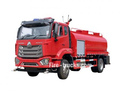
Brandweerwagens Brandweerlieden werken door de gecoördineerde werking van meerdere systemen om wateraanvoer, drukopbouw en brandbestrijding te realiseren. Inzicht in deze principes helpt brandweerlieden effectief te opereren in noodsituaties. » I. Hoe brandweerwagens werken: ▪ A. Pompsysteem: Het hart van de brandbestrijding: Het hart van elke brandweerwagen is de pomp. Deze krachtige unit zuigt water aan uit de tank aan boord of een externe bron – zoals een brandkraan, meer of vijver – en pompt het onder hoge druk door slangen. De meest gebruikte pomp is de centrifugaalpomp, die gebruikmaakt van een roterende waaier om water onder druk te zetten en te verplaatsen. Brandweerlieden regelen de waterstroom met behulp van een reeks hendels en meters op het pomppaneel. Ze kunnen de druk naar behoefte aanpassen en water gelijktijdig naar meerdere slanglijnen leiden. Pomptype Kenmerken Beste toepassing Eentraps centrifugaalpomp Hoge doorstroming, matige druk Algemene gemeentelijke brandbestrijding Tweetraps centrifugaalpomp Schakelbaar tussen volume en druk Hoge gebouwen, lange slangen liggen Meertrapspomp Zeer hoge druk Industriële installaties, schuimsystemen ▪ Belangrijkste pompparameters: › Debiet: 1.200 - 6.000 liter per minuut (afhankelijk van het model) › Maximale druk: 1,0 - 2,5 MPa (10-25 bar) › Voorbereidingstijd: ≤30 seconden ▪ B. Watertank en opslagsysteem: › Tankinhoud: 500 - 1.500 gallons (ongeveer 2.000 tot 6.000 liter), afhankelijk van de grootte en het type voertuig. › Materiaal van de tank: corrosiebestendig roestvrij staal of gecoat koolstofstaal › Interne schotten: Meerdere compartimenten met een anti-overspanningsontwerp om waterbeweging te beheersen tijdens noodsituaties. › Vultijd: ≤3 minuten via brandkraan of aanzuiging › Waterniveau-indicator: Visuele meter aan de zijkant van de tank; optionele weergave in de cabine De tank is vervaardigd uit corrosiebestendige materialen, doorgaans roestvrij staal of gecoat koolstofstaal, met interne schotten die de waterdruk tijdens noodritten beheersen. ▪ C. Slang- en sproeiersystemen Brandweerwagens hebben diverse slangen met verschillende functies aan boord: › Aanvalsslang: 1,5 - 2,5 inch diameter — levert water direct aan de brandhaard › Toevoerslang: 4 - 5 inch in diameter — transporteert water van brandkranen of andere pompen. › Booster slang: slang met kleine diameter op haspel — gebruikt voor kleine branden zoals gras- of voertuigbranden Aan het uiteinde van de slang bevindt zich het mondstuk waarmee brandweerlieden de waterstraal kunnen regelen en de druk, het sproeipatroon en de richting kunnen aanpassen aan het type brand. ▪ D. Brandmonitor › Watermonitor: Levert een krachtige waterstraal voor grootschalige brandbestrijding; vast of op afstand bedienbaar › Droogpoedermonitor: Verspreidt droog chemisch poeder voor branden met brandbare vloeistoffen, gassen en elektrische installaties. › Combinatiemonitor: Kan zowel water als droog poeder afvoeren; schakelt indien nodig tussen de medi...
Details
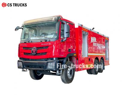
Als meest professionele Isuzu-brandweerwagenfabriek is het kernontwerp van de Isuzu NPR-brandweerwagen met waterschuim de integratie van een schuimblussysteem in een watertankwagen. Dit resulteert in een gecombineerde brandblusinstallatie die zowel water als schuim kan spuiten. De wagen kan zelfstandig branden blussen, een water- of schuimmengsel naar andere apparatuur transporteren en is geschikt voor gebruik in droge en waterarme gebieden. ★ Technisch Specificatie Alle brandweerwagens van CS Trucks, 100% gebaseerd op de wensen van de klant. Capaciteit Motormodel Water Schuim Brandweerpomp Brandmonitor 2500 liter ISUZU 4HK1 / 19 0 pk 2500 liter 500L CB10/40 Brandweerpomp PL8/32 2026 officiële ISUZU brandweerwagen cabine chassis vrachtwagen Originele tekening van het chassis van de brandweerwagen uit 2026 Item Ontwerpdetails van Isuzu brandweerwagens Ontwerpkern Integreert een schuimblussysteem in een watertankwagen, waardoor een brandweervoertuig met dubbele functionaliteit ontstaat dat zowel water als schuim kan spuiten. Kenmerken zijn onder meer: • Onafhankelijke brandbestrijding • Toevoer van water of schuimmengsel naar andere apparatuur • Geschikt voor droge of waterarme gebieden, waardoor multifunctioneel gebruik mogelijk is. Algemeen ontwerpconcept Dit voertuig is ontworpen om te voldoen aan de brandbestrijdingsbehoeften in werkplaatsen en omliggende gebieden, met verbeterde mogelijkheden voor branden veroorzaakt door olie, elektriciteit en vaste materialen. Het bestaat uit een chassis en gespecialiseerde carrosserie-uitrusting, waarbij de nadruk ligt op betrouwbaarheid, multifunctionaliteit en gebruiksgemak. Chassisselectie • Maakt gebruik van beproefde chassis van het type II voor middelzware of zware toepassingen • Vierwielaandrijving wordt aanbevolen voor betere mobiliteit en tractie op moeilijk begaanbaar terrein. Nieuw ontwerp van de Isuzu 700P waterbrandweerwagens voor 2026 Kerncomponenten van het systeem en belangrijke ontwerppunten 1. Watertank & Schuimvloeistoftank • Materiaal: Roestvrij staal, corrosiebestendig • Aanbevolen capaciteit: Watertank 3000–5000 liter, schuimvloeistoftank 300–600 liter • Structurele optimalisatie: Interne schotten scheiden de water- en schuimkamers, die via aansluitpoorten kunnen worden omgeschakeld naar een modus met één watertank, waardoor multifunctioneel gebruik mogelijk is. 2. Schuimdoseersysteem • Maakt gebruik van een drukregelaar met gebalanceerde druk (kerncomponent) om water en schuimconcentraat nauwkeurig te mengen in verhoudingen van 3% of 6%. • Stabiele output die niet wordt beïnvloed door schommelingen in debiet of druk, geschikt voor niet-gespecialiseerde gebruikers. • Uitgerust met een externe schuimzuigopening voor aanvulling op locatie. 3. Afvoersysteem • Brandweerpomp: Zeer efficiënte, energiebesparende meertraps centrifugaalpomp, debiet ≥ 4 0 L/S • Brandmonitor: Op afstand bedienbare water-/schuimmonitor met dubbele functie, bereik ≥50 meter, verstelbare hoek • Biedt ondersteuning v...
Details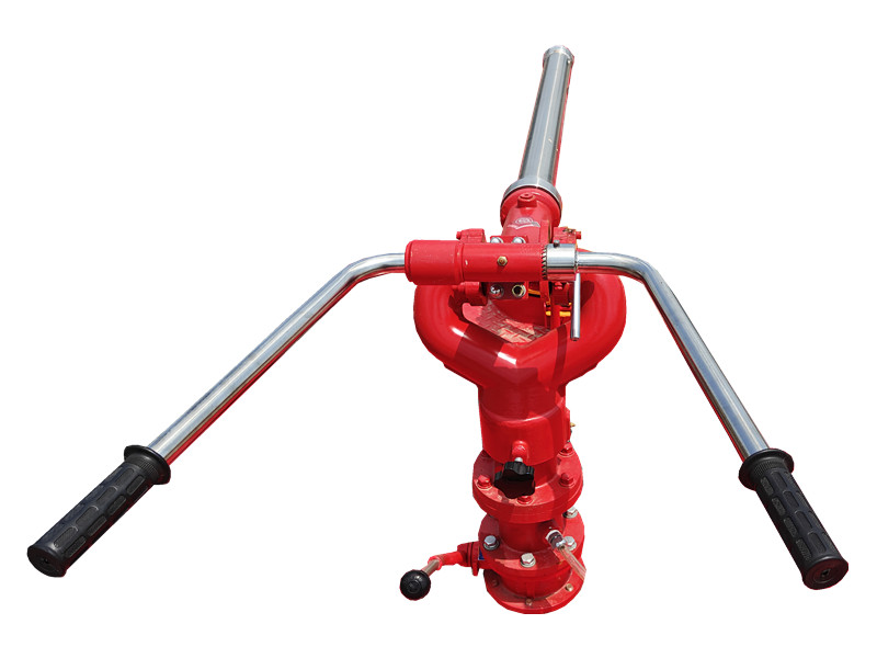
De PF5-15 vaste droge poedermonitor Het maakt gebruik van droog poeder als medium en vertrouwt op een vaste basis voor een stabiele sproeistroom. Het is geschikt voor chemische en magazijnomgevingen en kan het brandende oppervlak in de beginfase van een brand snel bedekken, waardoor de blusefficiëntie wordt verbeterd. De PF5-15 vaste droge poedermonitor Het apparaat heeft een robuuste constructie, is eenvoudig te bedienen en kan worden gekoppeld aan een automatisch besturingssysteem voor activering op afstand en nauwkeurig sproeien. » I. PF5-15 vaste droge poedermonitor structuur: Kenmerken van de PF5-15 vaste droge-poeder monitor: ● Volledig functioneel; ● Eenvoudige en originele structuur; ● Stabiele prestaties en eenvoudig onderhoud; ● Lage inlaatdruk; ● Voorzien van een automatische aftapkraan met horizontale en verticale vergrendelingsfuncties; ● Materiaal: Nauwkeurig gegoten aluminiumlegering; ● Kanonkop: Aluminiumlegering. » II. Schuimkanon PL24 specificaties: Model Stroom ( kg /S ) Bereik ( M ) Nominale werkdruk ( MPA ) Pitch rotatie ( ° ) Horizontale rotatie ( ° ) L×B×H ( mm ) Gewicht ( Kg ) PF5-15/40 40 ≥42 0,80 -45 ~ +70 0 ~ 360 980x340x550 28.5 » III. Producttoepassingen: Brandweerwagen met PF5-15 vaste droge poedermonitor PF5-15 vaste droogpoedermonitor testen De PF5-15 stationaire droogpoederblusser heeft een groot sproeibereik en een breed dekkingsgebied, en kan snel een droogpoederblusbarrière vormen. Hij is geschikt voor vaste locaties zoals chemische fabrieken, oliedepots en opslagterreinen, en biedt continue en stabiele brandblusmogelijkheden voor grote gebieden.
Details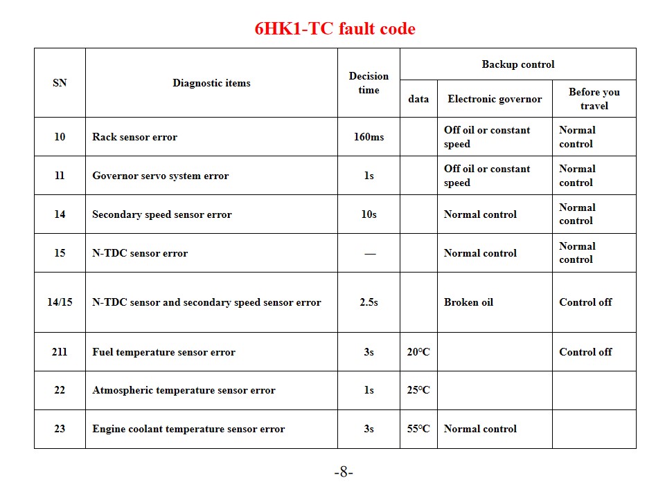
Isuzu 6HK1-TC brandweerwagens , ook wel genoemd Isuzu reddingsbrandweerwagen Diagnose en oplossingen voor motorfoutcodes. De Isuzu 6HK1-TC-motor maakt gebruik van het geavanceerde TICS-brandstofinjectiepompsysteem met elektronische regeling, en de ECU (Engine Control Unit) beschikt over zelfdiagnose. Wanneer het systeem een storing detecteert, gaat het waarschuwingslampje "CHECK ENGINE" branden en wordt de bijbehorende foutcode opgeslagen. Inzicht in de interpretatie en oplossingen voor deze foutcodes kan de efficiëntie van het motoronderhoud aanzienlijk verbeteren. Veelvoorkomende foutcodes en oplossingen Storingscodes P-serie P0101 (Lage spanning in het circuit van de luchtmassasensor) Controleer de koelvloeistofsensensor en de bijbehorende bedrading. Controleer de voedingsspanning van de sensor en de massa-aansluiting. Vervang indien nodig de ECU of de sensor. P0102 (Laserluchtstroomsensorcircuit te hoog) Controleer de brandstofkwaliteit en de staat van het filter. Reinig het brandstofsysteem. Controleer de brandstofdrukregelaar, de brandstofpomp en de injectorcircuits. P0103 (Laserluchtstroomsensor A, circuit te hoog) Controleer het sensorsignaalcircuit op kortsluiting. Test de werking van de sensor. Vervang de sensor of de ECU indien nodig. Digitale storingscodes 10 (Fout in de racksensor) Controleer de racksensor en de bijbehorende bedrading. Controleer of de signaaloverdracht normaal verloopt. 11 (Fout in het servosysteem van de snelheidsregelaar) Controleer de werkingsstatus van het servosysteem van de snelheidsregelaar. Test de bijbehorende circuitverbindingen. 14 (Fout in de hulpsnelheidssensor) Controleer de installatiepositie van de hulpsnelheidssensor. Test het signaal van de sensor. 15 (N-TDC-sensorfout) Controleer de N-TDC-sensoraansluiting. Controleer de nauwkeurigheid van het signaal. Systeemonderhoud en preventieve maatregelen SN Diagnostische items Beslissingstijd Back-upbesturing gegevens Elektronische regelaar Voordat u op reis gaat 10 Rack-sensorfout 160 ms Olievrij of constante snelheid Normale controle 11 Fout in het servosysteem van de regelaar 1s Olievrij of constante snelheid Normale controle 14 Fout in secundaire snelheidssensor 10 seconden Normale controle Normale controle 15 N-TDC-sensorfout — Normale controle Normale controle 14/15 Fout in de N-TDC-sensor en de secundaire snelheidsensor 2,5s Gebroken olie Bediening uit 211 Foutmelding brandstoftemperatuursensor 3s 20℃ Bediening uit 22 Fout in de atmosferische temperatuursensor 1s 25℃ 23 Foutmelding van de koelvloeistofsensor 3s 55℃ Normale controle Connector Terminal nr. Signaal Draaddikte/diameter (Kabelboom van de injectiepomp) SWP 8-aansluitingen Zwart 1 Aandrijfspanning van de regelaaractuator - 1 RM 2 2 Regelaarcircuit GND-1 W/1.2 3 Doelstelling rekpositie - 1 U1 2 4 Rackpositie spanning G/1.2 5 Regelaarcircuit 5V-1 Y/1.2 6 Reserve N-sensor (GND) BR/1.2 7 Reserve N-sensor (SIG) 0/1.2 8 Neertrekken B/1.2 SWP6- terminals Zwart G Aandrijfspanning van de regelaarac...
Details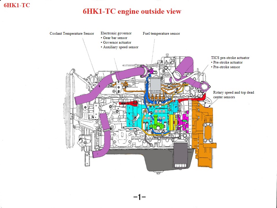
Isuzu 6HK1 brandweer- en reddingsvoertuigen , ook wel genoemd Isuzu brandweerwagen , Als de motor van een Isuzu-reddingsbrandweerwagen oververhit raakt, moeten de volgende onderdelen eerst worden gecontroleerd: 1. Koelsysteem: Problemen zoals een defecte ventilator, een verstopte radiator, een defecte thermostaat of onvoldoende koelvloeistof kunnen allemaal bijdragen aan oververhitting van de motor. 2. Oliekwaliteit en -hoeveelheid: Slechte oliekwaliteit of onvoldoende olie kan ook leiden tot oververhitting van de motor. 3. Mechanische defecten zoals een cilinderuitbarsting, scheuren in de cilinderwand of andere defecten kunnen dit verschijnsel ook veroorzaken. Als zware dieselmotor vereist de Isuzu 6HK1-motor strikte naleving van de technische specificaties voor onderhoud. De belangrijkste punten zijn als volgt: 1. Structureel inzicht en specificaties voor demontage en montage Krukas-drijfstangmechanisme De cilinderbus heeft een losse passing, waardoor speciaal gereedschap nodig is om te voorkomen dat deze er tijdens demontage en montage uitvalt. De standaard speling bedraagt 0,122–0,156 mm. De buitendiameter van de zuiger heeft een nauwe tolerantie (114,894–114,909 mm). Let tijdens de installatie op de openingsrichting van de zuigerveer en de afstelling van de "drie spelingen" (eindspeling, zijdelingse speling en achterspeling). Het onderste carter is een constructie uit één stuk en moet tijdens onderhoud omhoog gehesen worden om vervorming te voorkomen. Afstelling van het timingsysteem Tijdens de montage van de versnellingsbak moeten de markeringen op het krukastandwiel en het tussenwiel worden uitgelijnd. De B-markering op de nokkenas moet gelijk liggen met het oppervlak van de cilinderkop. De motor moet zich in het bovenste dode punt van de compressieslag bevinden in de eerste cilinder. Bij het installeren van de brandstofinjectiepomp moet u de timingaanwijzer uitlijnen met de S-positie op de connector en de markering van de injectieversteller uitlijnen met de aanwijzer op de pomphuis. • De lineaire gelijkstroommotor duwt de spoel op en neer onder invloed van het uitgangssignaal van de besturingseenheid. • De drijfstang die op de spoelconstructie is gemonteerd, brengt de op- en neerwaartse beweging van de spoel over op het verbindingsblok, dat aan het uiteinde van de tandheugel is gemonteerd. Onder druk van het verbindingsblok beweegt de tandheugel naar links en rechts om de hoeveelheid ingespoten brandstof te regelen. Wanneer de spoelconstructie omhoog beweegt, duwt de drijfstang de tandheugel om de brandstofinjectie te verhogen; omgekeerd, wanneer de spoelconstructie omlaag beweegt, beweegt de tandheugel in de richting waarin de brandstofinjectie wordt verlaagd. De functie van de kolom is om de verticale beweging om te zetten in een horizontale beweging van de tandheugel. • Het koperen blok is op het bovenste deel van het verbindingsblok gemonteerd om een tandwielsensor te vormen. De tandwielsensor detecteert de tandwielslag en stuurt deze...
Details
Lees verder, blijf op de hoogte, abonneer je en laat ons vooral weten wat je ervan vindt.

 IPv6 Network ondersteund

 Nederlands
 English
 français
 Deutsch
 русский
 italiano
 español
 português
 العربية
 日本語
日本語 한국의
한국의 Türkçe
 Melayu
 ไทย
ไทย Tiếng Việt
 Indonesia
  中文
中文 қазақ
қазақ Filipino
 မြန်မာ
 српски